background image

BLD5/10 User Manual

BLDC50/100

 User Manual

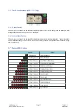
3.6  Two Potentiometers(

RS-232

 Only)

3.6.1  Speed Setting

This one potentiometer can be used for adjusting speed. The velocity range can be setting in BLD 

confi gurator. Its default range is 150 to 4500rpm. 

3.6.2  Acceleration Setting

This one potentiometer can be used for adjusting acceleration and deceleration. The acceleration 

and deceleration range are the same and can be setting in BLD confi guration. Their default range 

are 0 to 3000rps

2

3.7  Status LED Codes

Code

Error

Solid Green

Motor Disabled

Flashing Green

Motor Enabled

1 Red, 2 Green

Can’t Move (Disabled)

3 Red, 1 Green

Drive Over Temperature

3 Red, 2 Green

Bad Internal Voltage

4 Red, 1 Green

Supply Voltage High

4 Red, 2 Green

Supply Voltage Low

5 Red, 1 Green

Over Current

5 Red, 2 Green

Over Load

6 Red, 1 Green

Open Motor Phase

6 Red, 2 Green

Bad Hall Signal 

7 Red, 1 Green

Comm Error

7 Red, 2 Green

Save Failed

ACC/DEC

SPEED

Lin Engineering 

BLDC 50/100 Driver Manual

Page 21

Version 1.0 

01/29/2020

Summary of Contents for BLDC100

Page 1: ...BLDC50 100 BRUSHLESS DC MOTOR DRIVE USER MANUAL Lin Engineering BLDC 50 100 Driver Manual Version 1 0 01 29 2020 ...

Page 2: ...cting to a PC using RS 485 CN5 8 3 4 IO Control and Function Description 11 3 5 Connecting the Inputs and Outputs CN4 15 3 5 1 Input Connection 15 3 5 2 Dip Switches 19 3 5 3 Output Connection 20 3 6 Two Potentiometers RS 232 Only 21 3 6 1 Speed Setting 21 3 6 2 Acceleration Setting 21 3 7 Status LED Codes 21 4 Operation 22 4 1 Basic operation 22 4 2 Setting the acceleration and deceleration 23 5 ...

Page 3: ...igital control signal RS 232 485 communication command or MMI control High response of the PID velocity loop and D Q current loop control Brushless sinusoidal current control With motor phase compensation The drive can supply 5 10A rms maximum continuously current for each motor phase And the twice over load 10 20A is allowed for 5 seconds With eight single ended optically isolated inputs 5 24V wh...

Page 4: ...0 01D RO BL17E40 02 RO BL17E40 02D RO BL23E22 01 RO BL23E22 01D RO BL23E22 02 RO BL23E22 02D RO BL23E33 01 RO BL23E33 01D RO BL23E33 02 RO BL23E33 02D RO BL23E48 02 RO BL23E48 02D RO 1 2 3 Brushless DC Motor Cable P N Length L BLDC Extension 1m 1m BLDC Extension 3m 3m L 20 Connector Molex Connector Molex Connector Molex Connector Molex 300 20 Connector JST Housing PUDP 18V S Crimp SPUD 001T P0 5 1...

Page 5: ... X1 CW CCW X2 STDM X3 EN RE X4 SPST X5 STP X6 M0 X7 M1 ANALOG AL Optical Isolation Software Filter Status LED SPD Address ACC DEC RS 232 RS 485 IGBT PWM Power Amplifier DSP MOTOR HALL RS 232 RS 485 PC Setting Display Key Status Status BLDC50 100 X8 M2 AH MMI Setting Display Key MMI MENU ENT Lin Engineering BLDC 50 100 Driver Manual Page 5 Version 1 0 01 29 2020 ...

Page 6: ... where metal particles can fall into it 3 Connections To use the BLDC50 100 Drive the following items are needed DC input of 12 to 48VDC Direction Stop Mode STMD Enable Speed Setting Stop Analog or multi speed setting A compatible Brushless Motor 65 Uint mm 100 30 92 20 CN5 CN4 CN3 CN2 CN1 CN1 CN2 CN3 CN4 CN5 Speed Setting Connector to RS 232 I O Connector Motor Connector LED LED Acceleration Sett...

Page 7: ...rding to the diagram on the right Use 16 AWG wire for V and V Use 16 AWG for Earth Ground G Care should always be taken when working with voltages The BLDC50 100 contains an internal 15A fast acting fuse The BLDC50 100 series drives are designed to give optimum with the BLDC50 100 drive The R88A RR08050S can be purchased from Digi Key If you choose an unregulated power supply make sure the no load...

Page 8: ...ng to buy a USB to RS 232 converter The RS 232 circuitry does not have any extra electrical hardening and care should be taken when connecting to the RS 232 port as hot plugging could result in circuit failure If this is a con cern the RS 485 version should be used 3 3 2 Connecting to a PC using RS 485 CN5 RS 422 485 communication allows connection of more than one drive to a single host PC PLC HM...

Page 9: ...e system never needs to disable its transmitter software is simpli fied Some converters make this process very difficult to implement and can delay communica tions NOTE If the PC does not have an RS 485 serial port a converter is required You can contact Lin Engineering to buy a USB to RS 485 converter Two Wire Configuration In a 2 wire system the host must disable its transmitter before it can re...

Page 10: ...n configured click the Upload button so that the BLD Configurator settings match those of the drive Click on the Motion button and se lect the SCL operating mode The numerals 0 9 or the special characters may be used as addresses Make sure each drive on the network has a unique address Once the address has been assigned click Download to save the settings to the drive Address SCL Character Address...

Page 11: ...connection can dial to select 3 INPUT CW CCW X1 Clockwise Counter Clockwise Select 5 STMD STOP MODE X2 Stop mode choice input 7 EN RE Enable Reset X3 Motor enable disable It can be used for alarm reset as well 9 SPST SPEED SET X4 Internal external speed set choice 11 STOP X5 The electromagnetic brake operation is selected when the motor is stopped 13 M0 X6 For multi speed operation the M0 M1 M2 si...

Page 12: ... terminals X1 to X8 and the two output signal terminals Y0 and Y1 Y1 Y2 can be allocated as Fault Speed Out MOVE VA Fault2 Warning TLC IDLE 8 in total Input Signals Description The signal state represents the ON Carrying current or OFF Not carrying current state of the internal photocoupler rather than the voltage level of the signal CW CCW Switching the CW input will cause the motor to turn clock...

Page 13: ... Signal Description FAULT FAULT output an error signal when the drive is over heat over current over voltage under volt age or internal voltage bad The output voltage of error signal can be defined by SCL command AO SPEED OUT The motor output shaft output 6 pole pairs per revolution default And the pulse number can be set through the software MOVE This signal is output during motor rotation VA Spe...

Page 14: ...MF voltage is over range a warning will happen till the error is eliminated TLC When the output torque reaches the rated limi the output is ON IDLE IDLE can be configured as a general output when idle Lin Engineering BLDC 50 100 Driver Manual Page 14 Version 1 0 01 29 2020 ...

Page 15: ...CW 5V 17 15 13 11 9 7 5 3 1 18 16 14 12 10 8 6 4 2 INCOM AGND AIN 5V SPO SPO FLT FLT GND CN4 CONTACTS JST SPUD 001T P0 5 HOUSING JST PUDP 18V S Connect to CN4 INCOM COMMON CATHODE COMMON ANODE CW CCW STMD EN RE SPST STP M0 M1 M2 AGND AIN 5V FLT FLT SP0 SP0 18 0 V 0 V 8 SW1 OFF 5V 10 4 6 12 14 16 3 5 7 9 11 13 15 17 Signal Conditioning 3K inside drive Connecting to control IO with external Sinking ...

Page 16: ... STMD EN RE SPST STP M0 M1 M2 AGND AIN 5V FLT FLT SP0 SP0 18 8 10 4 6 12 14 16 3 5 7 9 11 13 15 17 Signal Conditioning SW1 OFF 0 V 5 24V 5V 3k Connecting to control IO with external Sourcing Outputs 1 6mA Lin Engineering BLDC 50 100 Driver Manual Page 16 Version 1 0 01 29 2020 ...

Page 17: ...PST STP M0 M1 M2 GND AGND AIN 5V FLT FLT SP0 SP0 18 8 10 4 6 12 14 16 3 5 7 9 11 13 15 17 2 Signal Conditioning 3K inside drive SW1 ON SW2 OFF 5V 0 V Connecting to control IO with internal Sinking Outputs Lin Engineering BLDC 50 100 Driver Manual Page 17 Version 1 0 01 29 2020 ...

Page 18: ... STP M0 M1 M2 AGND AIN 5V FLT FLT SP0 SP0 18 8 10 4 6 12 14 16 3 Switch or relay 5 7 9 11 13 15 17 Signal Conditioning 3K inside drive SW1 ON SW2 ON Connecting to control IO with internal Sourcing Outputs 5V Lin Engineering BLDC 50 100 Driver Manual Page 18 Version 1 0 01 29 2020 ...

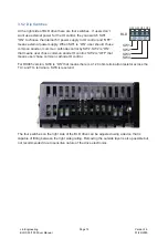
Page 19: ...ose common anode IO control SW2 is OFF that means user chose common cathode IO control For RS485 version SW4 is ON that means there is a 120 ohm termination resistor across the TX and TX terminals SW3 is reserved SW1 SW2 SW3 SW4 BLD OFF OFF OFF OFF The four switches on the right side of the BLD drive can be adjusted using a device that is capable of fitting between the right side grating Removing ...

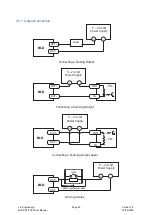
Page 20: ... Power Supply Driving a Relay 1N4935 suppression diode relay BLD BLD OUT OUT OUT OUT IN COM 5 24 volt Power Supply BLD Connecting a Sourcing Output again PLC OUT OUT IN COM 5 24 volt Power Supply Load BLD Connecting a Sinking Output OUT OUT Lin Engineering BLDC 50 100 Driver Manual Page 20 Version 1 0 01 29 2020 ...

Page 21: ...d can be setting in BLD configuration Their default range are 0 to 3000rps2 3 7 Status LED Codes Code Error Solid Green Motor Disabled Flashing Green Motor Enabled 1 Red 2 Green Can t Move Disabled 3 Red 1 Green Drive Over Temperature 3 Red 2 Green Bad Internal Voltage 4 Red 1 Green Supply Voltage High 4 Red 2 Green Supply Voltage Low 5 Red 1 Green Over Current 5 Red 2 Green Over Load 6 Red 1 Gree...

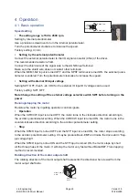
Page 22: ...ge selector switch SW1 before turning on the power Running stopping the motor Run stop the motor by inputting operation control signals Operation When the CW CCW input is turned OFF the motor turns in the clockwise direction according to the acc dec potentiometer setting When the CW CCW input is turned ON the motor turns in the counterclockwise direction according to the acc dec potentiometer sett...

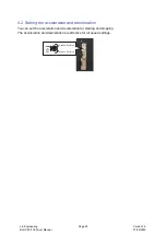
Page 23: ...ration You can set the acceleration and deceleration for starting and stopping The acceleration and deceleration are effective for all speed settings Gradual Run Stop ACC DEC Sudden Run Stop Lin Engineering BLDC 50 100 Driver Manual Page 23 Version 1 0 01 29 2020 ...

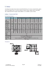
Page 24: ...m 72 72 144 144 215 215 Max torque Tmax mNm 144 1 67 0 81 1 62 3 34 144 288 288 1 63 3 26 430 4 92 9 84 430 Rated current I Arms 2 4 4 8 Max current Imax Arms Voltage constant 10 Vrms Krpm 2 65 5 2 7 6 56 3 28 5 2 2 65 5 5 Torque constant 10 Nm Arms 0 037 0 075 0 037 0 075 0 037 0 075 Moment of inertia 10 4kgm 2 0 0388 0 0388 0 072 0 072 0 114 0 114 Resistance 10 25 R Ω 1 03 3 4 0 45 1 73 0 25 0 8...

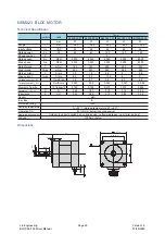
Page 25: ...ax Arms 6 2 3 2 6 9 Voltage constant 5 Vrms Krpm 3 4 6 7 3 2 6 7 6 8 Torque constant 5 Nm Arms 0 045 0 09 0 042 0 097 0 096 Moment of inertia 10 4kgm 2 0 148 0 148 0 279 0 279 0 456 Resistance 10 25 R Ω 0 48 1 80 0 18 0 76 0 44 Inductance L mH 0 45 0 64 0 18 0 84 0 54 Sensor Hall Ins class E Protective rating IP40 Operating temperature 0 50 storage temperature 20 60 Operating RH 85 RH or below non...

Page 26: ...0 4 86 14 98 Voltage constant 5 Vrms Krpm 3 44 7 3 7 2 7 3 Torque constant 5 Nm Arms 0 048 0 099 0 095 0 096 Moment of inertia 10 4kgm 2 0 38 0 38 0 74 1 08 Resistance 10 25 R Ω 0 18 0 71 0 27 0 20 Inductance L mH 0 34 1 35 0 70 0 47 Sensor Hall Ins class E Protective rating IP40 Operating temperature 0 50 storage temperature 20 60 Operating RH 85 RH or below noncondensing Operating environment Ou...

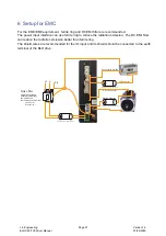
Page 27: ...ommended for the IO input and its shield should be connected to the earth terminal of the BLD drive Noise filter Used to eliminate external noise from the power line Recommanded filter model 5003 0316 1 Schurter Inc PE V V Motor Connector Place the ferrite ring near the drive Place the ferrite ring near the drive Place the ferrite ring near the drive HALL Connector I O Connector Connector to RS 23...

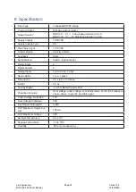
Page 28: ...Outputs 2 Analog Inputs 1 0 to 5 Vdc 12 bit Status LEDs 1 red 1 green Dimensions 3 9 x 2 6 x 1 2 inches Weight 6 0 oz Velocity Ripple 0 5 Rated Velocity Error Protection Function Over voltage under voltage over temperature short circuit phase to phase phase to grand bad Hall signal Under Voltage Protection 10V Over Voltage Protection 70V Input Signal Voltage IO 5 24V OUT Maximum Output Cur rent 10...

Page 29: ... techsupport linengineering com Our technical support group is glad to work with you in answering your questions If you can not find the solution to your particular application or if for any reason you need additional technical assistance please contact us Lin Engineering BLDC 50 100 Driver Manual Page 29 Version 1 0 01 29 2020 ...

Reviews: