background image

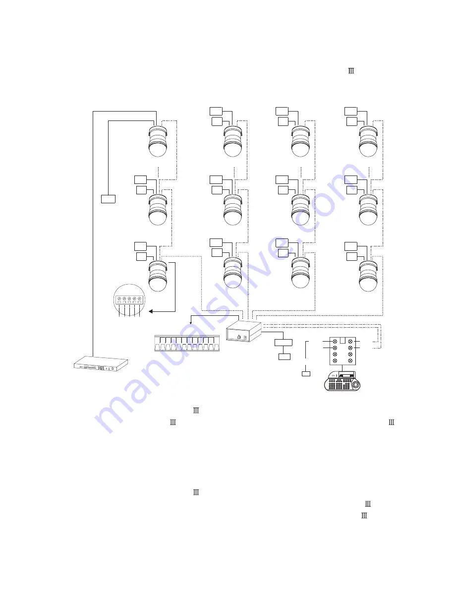
Multiple Domes means that more than one fast dome is linked in the system. Each dome connects

to next dome forming a serial linking. Each dome has an individual ID dip switch, which allows the

keyboard to identify each fast dome and make command. Sometimes it is more convenient to wire a

telemetry system in star configuration rather than daisy chain. To do this a PIH-804

data

distributor is necessary. It takes an output from a keyboard or a matrix and splits the single data line

into 4 separate data lines. One keyboard can control up to 64 camera.

RS-485 Connection Between PIH-804

Data Distributor and Fast Dome

RS-485 Connection Between PIH-804

Data Distributor and Keyboard

1st output TXDI1+ of PIH-804

connects to TXDI+ of 1st fast dome and TXDI1- of PIH-804

to

TXDI-of 1st fast dome.

Linking 2nd Fast Dome

TXDO+ of 1st fast dome connects to TXDI+ of 2nd dome and TXDO- of 1st dome to TXDI- of 2nd

dome.

7th pin TXDI+ of Connector Box connects to TXDO+ on RS-485 OUT jack of PIH-804

8th pin TXDI- of Connector Box connects to TXDO- on RS-485 OUT jack of PIH-804

Multiplexer

RS-485

ADAPTOR

AC

RS-485
DATA

CONTROL
CHAIN 1

CHAIN 2

CONTROL

CHAIN 4

CONTROL

CHAIN 3

CONTROL

(24VAC,100~240VAC)

AC

FAST
DOME

16

DOME

FAST

32

FAST
DOME

48

DOME

FAST

64

FAST
DOME

18

2

FAST
DOME

DOME

FAST

34

FAST
DOME

50

AC

VIDEO

OUT

VIDEO

AC

OUT

OUT

VIDEO

AC

VIDEO

AC

OUT

OUT

VIDEO

AC

VIDEO

AC

OUT

OUT

VIDEO

AC

OUT

VIDEO

33

FAST
DOME

1

DOME

FAST

17

DOME

FAST

FAST
DOME

49

VIDEO

AC

OUT

O1+

O1-

GND

O2+

O2-

GND

GND

O3-

O3+

O4+

GND

O4-

OUT

VIDEO

AC

VIDEO

AC

OUT

VIDEO

AC

OUT

DISTRIBUTOR

PIH-804

DAISY CONFIGURATION DIS

TRIBUTER

DC 12V

OUT

COLOR

MULTIPLEXER

1

2

3

4

POWER

ON

OFF

AUTO

TIME

MIN

MAX

C.SET

5

6

7

8

ENT

CAMERA

PLAY BACK

FRZ

9

4

1

TRIG

DCNT

ALARM

TXDI+

TXDI-

TXDO-

TXDO+

GND

ADAPTOR

Keyboard Controller

POWER

ALARM

R/T

06/02/15

12

00

00

PTZ MODE ID=000

1

8

2

7

3

6

4

5

AC

GND

DC12V

TXDI+

TXDI-

24

Summary of Contents for IPS0254

Page 1: ...L CSE D N SUPER HI RES FAST DOME CAMERA PIH 7625DH 7630DH 7635DH IPS1254 1258 1304 1308 1354 1358 Series D N SUPER HI RES FAST DOME IP CAMERA ST1254 1258 1304 1308 1354 1358 Series D N HUMAN TRACKING...

Page 2: ...DVR and Keyboard Fast Dome IP Camera with PC Control Initial Power Up Inspection Manual Operation Pan Tilt Control Fast Dome Selection Zoom Lens Control Focus Control Iris Control Horizontal 180 Inst...

Page 3: ...Mode Setting Auto Mode Setting Auto Scan Mode Setting Patrol Mode Setting Preset Function Setting Menu Tour Function Setting Menu Privacy Zones Setting Menu Alarms Setting Menu Password Function Menu...

Page 4: ...254 1258 1304 1308 1354 1358 LILIN s Fast Dome series are fully functional and user friendly It will meet your need for a wide range of surveillance applications The application for LILIN tracking dom...

Page 5: ...uto Switch from color to mono when light drops below 3 lux Schedule Switch from color to mono by time of setup 2 520 TV Lines Color 580 TV Lines Mono 3 0 1Lux Color 0 01Lux Mono 4 On Screen Setup Menu...

Page 6: ...ng object is near the center of FOV and its size is approximately smaller than 1 6 of FOV Zoom Out The size of moving object is approximately larger than 1 6 of FOV The position of moving object at th...

Page 7: ...cable and change the cable if there is damage on cable Violation may cause short circuit fire and injury 10 Make sure ground is well connected to avoid damage caused by lightning 11 Do not put any fo...

Page 8: ...Camera Case Bottom Chassis Power In Jack AC100 240V Power In Jack AC24V RS 485 In Out Terminal Video Out Jack Alarm In Out connector RJ45 Network Connector IPS1254 1258 1304 1308 1354 1358 STRUCTURAL...

Page 9: ...m Out Mode Switch RS 485 IN Terminal Resistor ON OFF RS 485 OUT Terminal Resistor ON OFF 2 wiring system HALF duplex or 4 wiring system Full duplex Transmission speed selection 1 Transmission speed se...

Page 10: ...ich include a check sum byte and extra control codes The check sum byte for example can prevent RS 485 interference affecting a protocol The extra control codes for example can provide the feature of...

Page 11: ...1 7 6 8 5 4 3 2 2 3 4 5 ON 8 6 7 5 4 3 2 7 6 8 ON 1 2 3 4 5 8 9 9 9 9 9 9 9 9 9 9 9 9 9 9 9 9 0 0 0 0 0 0 0 0 0 0 0 0 0 0 0 0 6 7 ON ON 1 2 3 4 5 8 6 7 1 1 5 4 3 2 7 6 8 ON 5 4 3 2 ON 7 6 8 1 1 ON 2...

Page 12: ...5 5 5 5 5 5 5 5 5 5 5 5 5 5 5 4 4 4 4 4 4 4 4 4 4 4 4 4 4 4 4 3 3 3 3 3 3 3 3 3 3 3 3 3 3 3 3 2 2 2 2 2 2 2 2 2 2 2 2 2 2 2 2 7 7 7 7 7 7 7 7 7 7 7 7 7 7 7 7 6 6 6 6 6 6 6 6 6 6 6 6 6 6 6 6 8 8 8 8 8...

Page 13: ...5 5 5 5 5 5 4 4 4 4 4 4 4 4 4 4 4 4 4 4 4 4 3 3 3 3 3 3 3 3 3 3 3 3 3 3 3 3 2 2 2 2 2 2 2 2 2 2 2 2 2 2 2 2 7 7 7 7 7 7 7 7 7 7 7 7 7 7 7 7 6 6 6 6 6 6 6 6 6 6 6 6 6 6 6 6 8 8 8 8 8 8 8 8 8 8 8 8 8 8...

Page 14: ...3 3 3 3 3 3 3 3 3 3 3 3 3 3 3 2 2 2 2 2 2 2 2 2 2 2 2 2 2 2 2 7 7 7 7 7 7 7 7 7 7 7 7 7 7 7 7 6 6 6 6 6 6 6 6 6 6 6 6 6 6 6 6 8 8 8 8 8 8 8 8 8 8 8 8 8 8 8 8 9 9 9 9 9 9 9 9 9 9 9 9 9 9 9 9 0 0 0 0 0...

Page 15: ...nt To Monitor To PIR Copper Wire AWG Length of Cable approx m ft 24 0 22mm 2 20 65 22 0 33mm 2 30 100 20 0 52mm 2 45 160 18 0 83mm 2 75 260 Accessory Connector Information PIN 1 2 3 4 Power AC24V Live...

Page 16: ...out signal to next fast dome through twisted pair cable Transmission Distance Max 1 Kilometer 4 Video Out BNC Jack Video Signal Output CVBS 1 0Vp p 75 BNC Recommend Data Cable 5C2V 5 Alarm In Out Con...

Page 17: ...Indoor Installation Structural Drawing Embedded Mounting Attached Mounting INSTALLATION 16...

Page 18: ...iameter and cut the circle Step 2 The Ceiling Ring Attach the ring to ceiling Ring size and screw location Tighten the three tapping screws into the ceiling or three machine screws with three screw nu...

Page 19: ...a body counter clockwise to tight position Step 5 The Fix Ring Put on the three L shape screw nuts Tighten the three black screws into the screw nuts Attach fix ring with screw nuts Step 6 Connection...

Page 20: ...ounting Fixed Ceiling Step 1 Fix The Base Turn the dome cover counter clockwise Untighten the two screws from base Separate the dome cover from camera Turn the camera cover clockwise Separate the came...

Page 21: ...n the two screws to fix the camera body Attach camera body to base position connector is correct or not Notice Turn camera body counter clockwise to tight position Step 4 Connection Connect RS 485 cab...

Page 22: ...ull control cable and power cable from bracket cable outlet Separate the camera body to the base Turn the camera cover clockwise Set all of control cables on the middle position and install rubber cov...

Page 23: ...screws to fix the camera body Attach camera body to base position connector is correct or not Notice Turn camera body counter clockwise to tight position Step 6 Install Dome Cover Put on dome cover to...

Page 24: ...h pin TXDI of Connector Box connects to TXDI of RS 485 jack on fast dome SYSTEM CONFIGURATION DVR Quad Switcher OR VIDEO OUT VIDEO OUT OUT VIDEO VIDEO OUT IN VIDEO IN VIDEO IN VIDEO RS 485 IN VIDEO IN...

Page 25: ...me connects to TXDI of 2nd dome and TXDO of 1st dome to TXDI of 2nd dome 7th pin TXDI of Connector Box connects to TXDO on RS 485 OUT jack of PIH 804 8th pin TXDI of Connector Box connects to TXDO on...

Page 26: ...Dome TXDO of 1st dome connects to TXDI of 2nd dome and TXDO of 1st dome to TXDI of 2nd dome 64 fast dome can be linked through the connection as shown 5th pin TXDO of 1st keyboard s connector box con...

Page 27: ...nd TXDO of 1st dome to TXDI of 2nd dome 64 fast domes can linked through the connection as shown Fast Dome with PC Control PC telemetry remote controls fast dome with standard RS 485 data format forma...

Page 28: ...ome DVR and Keyboard The DVR System is an advanced digital recording product with long recording time and easy searching features Telemetry remote control is twisted pair for data transmission to the...

Page 29: ...via RJ 45 Ethernet cable that provides both Internet and or Intranet access Multiple Fast Dome IP Cameras can be connected with in a Hub or multiple Hubs Please consult your network administrator for...

Page 30: ...Scan until an operator cancels it For setting Fast Dome IP Camera other features or functions please refer to H 264 IP instruction manual Manual Operation Pan Tilt Control To control the pan and tilt...

Page 31: ...her Focusing will stop when the key is released Push key The target will become nearer Focusing will stop when the key is released 1 Manual focus far 2 Manual focus near 3 Auto Focus Push key The lens...

Page 32: ...et positions Each preset stores the exact position of the camera and automatic pan tilt zoom focus and iris setting Once the data is set the preset can be recalled for viewing or the presets can be se...

Page 33: ...pleted the information must be stored or it will not be memorized by the system Push key followed by key two beeps will be heard confirming that data is stored Note For the first 16 presets on each do...

Page 34: ...th 14th 15th and 16th preset positions To set up group 1 Push key followed by key Ex To set Group 1 To set Group 2 3 To set Group 3 4 To set Group 1 2 3 To set Group 2 3 4 To set Group 1 2 3 4 1 2 3 4...

Page 35: ...n alarm signal is triggered the dome will go to the relevant position at 360 sec Make sure the first 6 preset positions are set to desired alarm areas Alarm input can be set to NC normally close or NO...

Page 36: ...y close that can activate the linked devices The way to remove alarm after alarm issue as below Push the joystick up down left right or adjust the lens to remove the alarm issue Push of the keyboard R...

Page 37: ...ILT ANGLE TIME DATE DATE FORMAT ZOOM SPEED AUTO MODE EDIT ID SCENE FILES DWELL TIME SPEED CLR PRESET FOCUS SPEED AUTO IRIS LEVEL ADVANCED SETTING EXPOSURE MODE AUTO ON AUTO INT GAMMA PEDESTAL MIRROR E...

Page 38: ...DWELL TIME SPEED IN MODE OUT ENABLE PASSWORD CAMERA EDIT PASSWORD ALL OUT TIME OUT SCHEDULE SETUP SYSTEM INFORMATION EXIT CAMERA RESET REBOOT SYSTEM BACK STARTUP AUTO OPTIONS DAYLIGHT SAVING TIME ALA...

Page 39: ...then press key to exit setup menu Camera Reset Press key into Setup Menu Push joystick down to select CAMERA RESET and then press key to restart camera Press key to exit setup menu or push joystick do...

Page 40: ...Character Setup Menu Press key into Setup Menu Push joystick down to select DISPLAY SETUP and then press key to display character setup menu Push joystick down to select BACK and then press key to go...

Page 41: ...stops when Alarm Input is triggered 5 10 15 20 25 30sec can be selected 4 Alarm Message Setting Push joystick down to select DATE TIME and then push joystick left or right to make selection OFF No Da...

Page 42: ...play elapsed time Auto pan will have been displayed on the monitor screen until elapsed time stops when auto pan is operated 5 10 15 20 25 30sec can be selected 7 Auto Pan Setting 8 Character Location...

Page 43: ...al focus mode switch to auto focus mode or performing camera zoom ratio is stopped 2 Zoom Speed Setting Push joystick down to select ZOOM SPEED and then push joystick left or right to adjust zoom spee...

Page 44: ...Manual Exposure Setting and then push joystick left or right to made selection 1 250 1 500 1 1000 1 2000 1 100000 1 10000 1 4000 1 60 50 1 100 120 1 250 1 500 1 1000 1 100000 1 10000 1 4000 1 2000 AU...

Page 45: ...TRL1 5 Day Night Setting Push joystick down to select DAY NIGHT and then push joystick left or right to select mode AUTO When light level is over 10 lux camera switches DAY automatically to produce co...

Page 46: ...t the item has to be set Note Select current night illuminator setting can more focus on object C SET CTRL1 C SET CTRL1 7 Synchronization Mode Setting Push joystick down to select SYNC MODE and then p...

Page 47: ...be Left Right reverse 4 Y Negative Setting Push joystick down to select Y NEGATIVE and then push joystick left or right to make selection OFF or ON Note This function inverse the Y signal 5 Resolutio...

Page 48: ...ETURN MODE and then push joystick left or right to select return mode OFF NO action HOME Perform return home position mode SCAN Perform auto scan mode SEQ Perform preset group mode TOUR1 Perform tour1...

Page 49: ...e Setting Push joystick down to select DWELL TIME and then push joystick left or right to select dwell time 1 255 sec 3 Scan Speed Setting Push joystick down to select SCAN SPEED and then push joystic...

Page 50: ...me setting menu push joystick down to select PRESETS and then press key into presets setting menu 1 Display the Preset Setting Menu PRESETS PRESET NUMBER PRESET MAP EDIT POSITION EDIT ID SCENE FILES D...

Page 51: ...COMMAND 1 New Preset ID Editing Push joystick down to select character and press key to confirm The character selected will be showed in edit area If you need space push joystick down to select SPACE...

Page 52: ...LANCE BACK EXIT AUTO ATW EXPOSURE MODE AUTO MANUAL WHITE BALANCE ATW PUSH MWB Note When scene file of preset is ON it will be part of preset parameters C SET CTRL1 Push joystick down to select DWELL T...

Page 53: ...sets Push joystick left or right to select preset 1 128 Press key to confirm and push joystick to select BACK then press key again to back to tours setting or push joystick to select EXIT and press ke...

Page 54: ...l zoom lens and auto focus lens and then press key to confirm and get into privacy zone mask area for editing Press key and then push joystick left right up or down to extend privacy zone mask area Pr...

Page 55: ...rm memory patrol mode TRACK Perform human tracking mode The tracking functions are only for tracking models ST1254 1258 1304 1308 1354 1358 Note 1 When alarm input is tracking mode if alarm happen the...

Page 56: ...ON or OFF 2 Password Setting Push joystick down to select EDIT PASSWORD and then press key into edit password setting Push joystick left or right to select number 1 9 and then press key to confirm Th...

Page 57: ...vious passwords have to enter on the setting menu first and then do modifying password 4 Modify Password C SET CTRL1 C SET CTRL1 After password function is ON press key to display frame of input passw...

Page 58: ...ctory initialization for all Note PLEASE WAITING FACTORY INITIALIZATION will show on the screen after confirmation 2 Factory Initial for All C SET CTRL1 C SET CTRL1 C SET CTRL1 PLEASE WAITING FACTORY...

Page 59: ...edule Setting Menu ALARM IN STARTUP START END BACK EXIT OFF 00 00 00 00 Push joystick down to select STARTUP and then push joystick left or right to select ON or OFF OFF Alarm input schedule function...

Page 60: ...00 01 00 2 Schedule Time Setting Push joystick down to item 1 to 8 and complete time setting and then get into auto setting Then push joystick left or right to select auto mode and press key to confi...

Page 61: ...EXIT START 4 END 5 START 6 END Push joystick down to select STARTUP and then push joystick left or right to select ON or OFF 2 Start Daylight Saving Time Function Setting OFF 07 03 01 14 00 08 03 01 1...

Page 62: ...16 presets 1 64 ID setting Protocol is MLP1 1 256 ID setting Protocol is MLP2 Camera Image Device Horizontal Vertical Pixel Scanning System Horizontal Resolution Minimum Illumination S N Ratio Synchro...

Page 63: ...D 57 8 H 43 7 V T 2 60 D 2 10 H 1 53 V f 3 43 120mm F1 6 wide F4 5 telephoto W 68 6 D 57 8 H 43 7 V T 2 23 D 1 70 H 1 30 V Electrical Power Supply Power Consumption Control Interface RS 485 Voltage Al...

Page 64: ...atrol Learn Mode Stop Password Activate Password Edit Password Single Preset Position Delete Numeric Key CAM ZOOM IN ZOOM OUT FOCUS FAR FOCUS NEAR AUTO FOCUS IRIS O IRIS C AUTO IRIS 180 REV Numeric Ke...

Page 65: ...nection on keyboard 3 4 Check if the fast dome is under Auto Pan mode Please deactivate the Auto Pan 3 5 Check if alarm is triggered Cancel triggered alarm 4 1 Dusts on dome cover or housing cover Cle...

Page 66: ...APPENDIX C Preset ID Characters Table 1 1 1 2 2 2 3 3 4 5 6 4 5 6 0 A N a n 1 B O b o 2 C P c p 3 D Q d q 4 E R e r 5 F S f s 6 G T g t 7 H U h u Page 2 Page 3 Page 1 8 I V i v 9 J W j w K X k x L Y...

Page 67: ...MERIT LILIN ENT CO LTD http www meritlilin com 66 7625CSE...

Reviews: