background image

Typographic and iconographic conventions

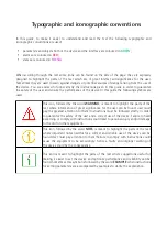
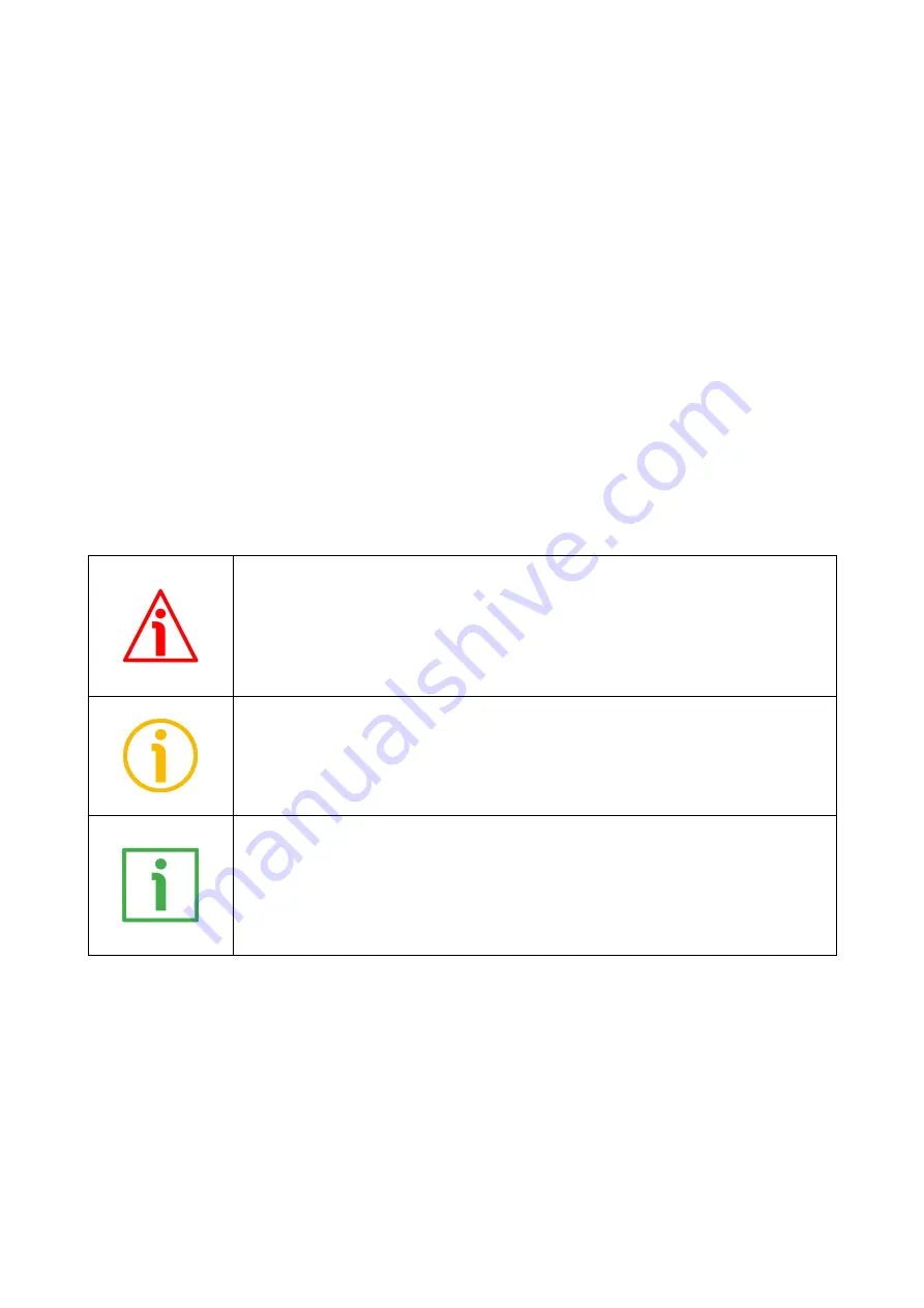
In   this   guide,   to   make   it   easier   to   understand   and   read   the   text   the   following   typographic   and
iconographic conventions are used:

parameters and objects both of the device and the interface are coloured in 

GREEN

;

alarms are coloured in 

RED

;

states are coloured in 

FUCSIA

.

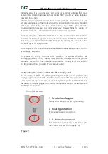
When scrolling through the text some icons can be found on the side of the page: they are expressly
designed to highlight the parts of the text which are of great interest and significance for the user.
Sometimes they are used to warn against dangers or potential sources of danger arising from the use of
the device. You are advised to follow strictly the instructions given in this guide in order to guarantee
the safety of the user and ensure the performance of the device. In this guide the following symbols are
used:

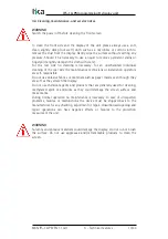
This icon, followed by the word 

WARNING

, is meant to highlight the parts of the

text where information of great significance for the user can be found: user must
pay the greatest attention to them! Instructions must be followed strictly in order
to guarantee the safety of the user and a correct use of the device. Failure to heed
a warning or comply with instructions could lead to personal injury and/or damage
to the unit or other equipment.
This icon, followed by the word 

NOTE

, is meant to highlight the parts of the text

where important notes needful for a correct and reliable use of the device can be
found. User must pay attention to them! Failure to comply with instructions could
cause the equipment to be set wrongly: hence a faulty and improper working of
the device could be the consequence.

This icon is meant to highlight the parts of the text where suggestions useful for
making it easier to set the device and optimize performance and reliability can be
found. Sometimes this symbol is followed by the word 

EXAMPLE

 when instructions

for setting parameters are accompanied by examples to clarify the explanation.

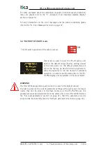
Summary of Contents for IFS-10-PM

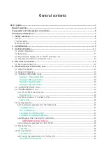
Page 1: ...save and load the parameters Suitable for the following models IFS 10 PM General Contents Preliminary information 7 1 Safety summary 8 2 Identification 10 3 Technical features 11 4 Electrical connecti...

Page 2: ...on herein is subject to change without notice and should not be construed as a commitment by Lika Electronic s r l Lika Electronic s r l reserves the right to make all modifications at any moments and...

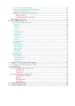
Page 3: ...AL OPERATION mode 16 Display 1 Frequencies Hz 16 Display 2 Divergence 16 Display 3 Scaled Input 1 16 Display 4 Scaled Input 2 16 5 4 FACTORY SETTINGS mode 17 5 5 PROGRAMMING mode 18 5 5 1 IFS 10 PM me...

Page 4: ...isor 2 29 Value 2 30 Units 2 30 Decimal Point 2 30 Unit Settings 31 Display Mode 31 Screen Light 31 Screen Saver 31 PIN Value 31 Touch Tones 31 Serial Settings 33 Unit Number 33 Serial Baud Rate 33 Se...

Page 5: ...rom Display Memory 21 Load Data From Safety Unit 21 P PIN Value 31 Please Confirm 25 R Readback Error 38 Runtime Error 37 S Safety unit 19 Save Data To Display Memory 24 Save Data To Display Unit 24 S...

Page 6: ...nt to highlight the parts of the text where information of great significance for the user can be found user must pay the greatest attention to them Instructions must be followed strictly in order to...

Page 7: ...L switch settings Among the main features are touchscreen with intuitive navigation 1 54 OLED display 128 x 64 pixels simple parametrization of the safety unit editing saving and loading of parameter...

Page 8: ...ing the device connect according to the explanation in the 4 Electrical connections section on page 14 in compliance with the 2014 30 EU norm on electromagnetic compatibility following precautions mus...

Page 9: ...cal installation has to be carried out with power supply disconnected and stationary mechanical parts do not disassemble the unit do not tool the unit delicate electronic equipment handle with care do...

Page 10: ...nd the serial number when reaching Lika Electronic for purchasing spare parts or needing assistance For any information on the technical characteristics of the product refer to the technical catalogue...

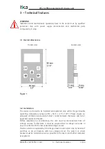
Page 11: ...Please ensure an adequate ventilation and avoid all direct contact between the device and hot or aggressive gases and liquids Before installation or maintenance the unit must be disconnected from all...

Page 12: ...rvoltages at the connections must be limited to values in accordance to the overvoltage category II For placement wiring environmental conditions as well as shielding and earthing grounding of the sup...

Page 13: ...perators are self responsible Do not use abrasive fabrics or materials such as paper towels even though they are soft as they scratch the display Do not use chemical agents and products that are gener...

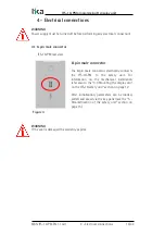
Page 14: ...ectrically connects the IFS 10 PM to the safety unit For information on the mechanical installation refer also to the 3 3 Mounting the display unit on the IFS 10 safety unit section on page 12 After i...

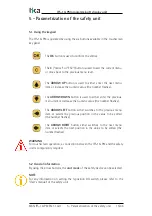
Page 15: ...ase the numeric value the number flashes The ARROW LEFT button either switches to the previous menu item or selects the previous position in the value to be edited the number flashes The ARROW RIGHT b...

Page 16: ...parameter in the Main menu of the safety unit The value depends on the scaling and divergence parameter settings of the safety unit Display 3 Scaled Input 1 In this mode the input frequency of the sen...

Page 17: ...arameters are set at the factory by Lika Electronic engineers to allow the operator to run the device for standard operation is a safe mode No data entry to the IFS 10 PM display unit is available in...

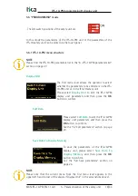
Page 18: ...it Please select Display Unit to edit the IFS 10 PM display unit parameters and then press the OK button to confirm Edit Data Please select Edit Data to edit the IFS 10 PM display unit parameters and...

Page 19: ...ta To edit already loaded parameters please select Use Loaded Data and then press the OK button to confirm See the 5 6 Load parameters section on page 21 Load Data From Safety Unit To load the current...

Page 20: ...button to confirm See the 5 8 Save parameters section on page 24 Save Data To Display Memory To save the parameters of the IFS 10 safety unit on the flash memory of the IFS 10 PM display unit please s...

Page 21: ...0 safety unit or the flash memory of the IFS 10 PM display unit To edit the already loaded parameters please select Use Loaded Data and then press the OK button to confirm Load Data From Safety Unit T...

Page 22: ...f the display unit the following warning message will appear ATTENTION No Data In Flash 5 6 3 Loading the parameters of IFS 10 PM The Load Data From menu is only available for the parameters of the IF...

Page 23: ...the arrow buttons The current value of the parameter appears on the display too After pressing the OK button the parameter can be edited By using the left right arrow buttons the cursor can be skipped...

Page 24: ...please select Save Data To Safety Unit and then press the OK button to confirm Save Data To Display Memory To save the parameters of the IFS 10 safety unit on the flash memory of the IFS 10 PM display...

Page 25: ...nu see on page 21 5 9 Entering the pin value Customarily the IFS 10 PM display unit is delivered without a PIN identification i e with PIN Value 0000 Thus the PIN Value request after initialization is...

Page 26: ...f the IFS 10 PM display unit keypad the PIN must be entered and confirmed by pressing the OK button WARNING Should the individual PIN be forgotten or lost you can enter the emergency pin 6079 MAN IFS...

Page 27: ...t Scaling for display 3 and 4 X Factor 1 1 999999 1 Divisor 1 1 999999 1 Value 1 999999 999999 0 Units 1 0 12 0 Decimal Point 1 0 5 0 X Factor 2 1 999999 1 Divisor 2 1 999999 1 Value 2 999999 999999 0...

Page 28: ...t Edit Data Settings Parameter Group Parameter Min Max Default Unit Settings Display Mode 1 3 1 Screen Light 0 99 0 Screen Saver 0 999 1 PIN Value 0 9999 0 Touch Tones 0 1 1 Serial Settings Unit Numbe...

Page 29: ...It set the divisor to be applied to the input frequency 1 before it is shown in the display mode 3 1 999999 1 Value 1 It sets the value to be added to subtracted from the input frequency 1 before it...

Page 30: ...ed with 2 in the name are applied to the input frequency 2 and used to show the value in the display mode 4 NOTE For some examples about the visualization of the values expressed in frequency speed pr...

Page 31: ...ED display 0 Display brightness minimum 99 Display brightness maximum 0 99 0 Screen Saver It sets the time expressed in minutes after which the screen saver is activated 0 screen saver OFF 1 screen sa...

Page 32: ...unit Changes in the Screen Light or Screen Saver parameter values are effective immediately but they are lost if not saved see the 5 8 Save parameters section on page 24 MAN IFS 10 PM EN 1 1 odt 6 IF...

Page 33: ...parity even stop bit 1 1 data bits 7 parity even stop bit 2 2 data bits 7 parity odd stop bit 1 3 data bits 7 parity odd stop bit 2 4 data bits 7 parity stop bit 1 5 data bits 7 parity stop bit 2 6 da...

Page 34: ...programming display unit to the user s settings Using a baud rate higher than 9600 baud the duration of the initialization procedure will be shortened MAN IFS 10 PM EN 1 1 odt 6 IFS 10 PM parameters l...

Page 35: ...Save parameters section on page 24 The calculation of an individual scalable display is made as follows The measuring unit see Units 1 Units 2 as well as the number of decimal digits see Decimal Poin...

Page 36: ...nformation on the parameters of the Input Scaling for display 3 and 4 group please refer to page 29 For any information on the Display 1 Frequencies Hz and the Display 3 Scaled Input 1 Display 4 Scale...

Page 37: ...ht next to the error message in the status line of the display All H values and their related error explanations are listed in the User s manual of the safety unit see the Error detection section EXAM...

Page 38: ...invoked to appear if corrupted data is found while saving data to or loading data from the flash memory Corrupted data cannot be loaded from the flash memory and used it needs to be saved again Readb...

Page 39: ...itive touch fields key tones switchable to mute Data memory Storage medium Data retention Flash EEPROM 1 000 000 cycles Housing Material Mounting Dimensions Protection class Weight front polycarbonate...

Page 40: ...1 Divisor 1 1 Value 1 0 Units 1 0 Decimal Point 1 0 X Factor 2 1 Divisor 2 1 Value 2 0 Units 2 0 Decimal Point 2 0 Unit Settings Display Mode 1 Screen Light 0 Screen Saver 1 PIN Value 0 Touch Tones 1...

Page 41: ...This page intentionally left blank...

Page 42: ...This page intentionally left blank...

Page 43: ...This page intentionally left blank...

Page 44: ...05 2016 First issue 01a 02a 1 1 05 05 2022 USB information removed address setting changing the scaled input new parameters added 02b 02c 03a 03b 04a Lika Electronic Via S Lorenzo 25 36010 Carr VI Ita...

Reviews: