Page 12 / 113
Section 2. Controls and connections
2. Controls and connections
2.1. MODEX concept
Code sequence
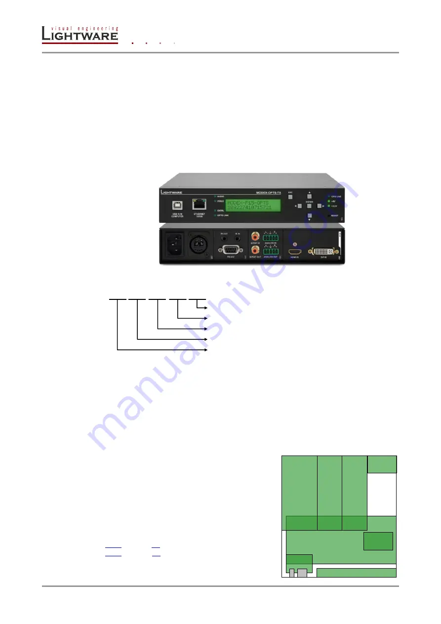
Each MODEX unit has a 15-character-long code sequence which identifies the modules
built in the frame. The code sequence consists of 5x3 blocks of characters. The
3-character-
long blocks are the last three characters of a module’s part code (this code is
also painted on the module/frame).
The following example represents the structure of the code sequence:
The module code
– that is displayed in idle state – of above MODEX unit is:
103
: (9161 0
103
) MODEX-OPTS-TX
Frame
227
: (9161 0
227
) MODEX-CON-NT-OPTS
Media connector
410
: (9161 0
410
) MODEX-AV-HDMI-DVI-4K-IM
Video & Audio Module (B)
715
: (9161 0
715
) MODEX-IF-RS232-IR
Interface Module (E)
721
: (9161 0
721
) MODEX-IF-AUD
Interface Module (D)
Info: The order of the modules and codes are determined by Lightware.
Module layout
The layout of the modules is fixed so as the order of
the module codes. B, D and E letters determine the
module positions which help to identify them in LW3
protocol.
C means the physical module (PHY), which is
integrated into the Core module in MODEX-OPT
extenders.
The letters are also displayed in the built-in website
in the Settings menu, Status submenu, see section
on page
, and Lock submenu, see in section
on page
103227410715721
Interface Module (D)
Interface Module (E)
Video & Audio Module (B)
Media connector
Frame
Core
Video
(B)
Interface
(D)
Interface
(E)
USB/Eth
Front Panel
Media
connector
PHY
(C)


