DA2DVI-Pro
User’s Manual Rev. 1.3
Page 17 / 43
3.
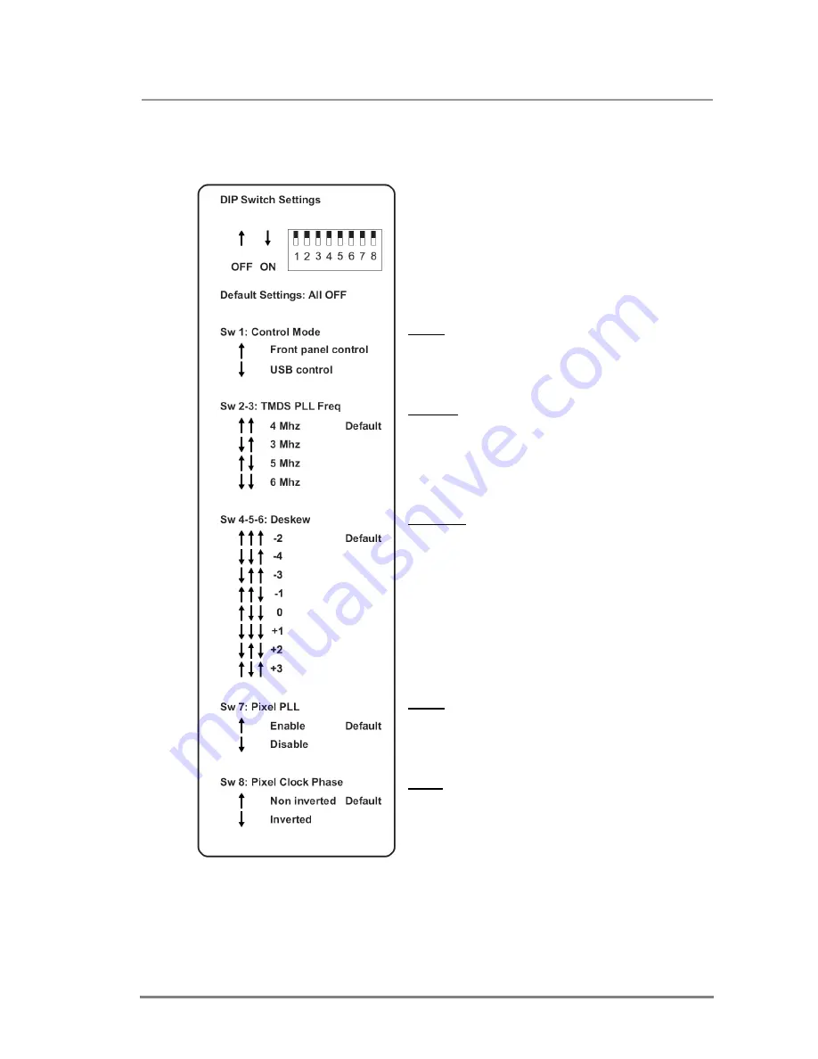
Front panel control - DIP switch settings
Advanced users can make adjustments using an 8
circuit DIP switch located on the rear panel of the
DA2DVI-Pro (see chapter 1.7.2).
SW 1:
defines whether the DA2DVI-Pro is controlled
by the rotary switches and the DIP switch or the
Lightware Matrix Controller software via USB
connection.
SW 2-3:
if the incoming signal has too much jitter
resulting from a low quality source, then a higher
TMDS PLL filter frequency may be necessary. The
default value of 4 MHz should provide the best results
in most cases. CAUTION! Setting a higher frequency
slightly decreases the quality of the output signal.
SW 4-5-6:
if the clock and pixel data are not perfectly
aligned in the internal pixel signal, then there’s a
possibility to add some skew between them in both
directions. There is no widely accepted value,
because it depends on the resolution and pixel clock.
A default setting of -2 should provide the best results
in most cases.
SW 7:
it is recommended to enable the Pixel PLL at
all times. If the quality of the incoming signal is too low
and the other settings could not improve the quality,
then disabling the Pixel PLL may be necessary.
SW 8:
this is a coarse way to adjust the deskew value.
This setting shifts the phase of the clock signal by 180
degrees.
Summary of Contents for DA2DVI-Pro
Page 1: ...DA2DVI Pro User s Manual ...
Page 2: ...Page 2 43 ...
Page 38: ...Page 38 43 7 Mechanical Drawings 7 1 Front view 42 mm 110 mm 7 2 Rear view 42 mm 110 mm ...
Page 39: ...DA2DVI Pro User s Manual Rev 1 3 Page 39 43 7 3 Top view 180 mm 110 mm ...
Page 43: ...DA2DVI Pro User s Manual Rev 1 3 Page 43 43 NOTES ...


