Page 14 / 43
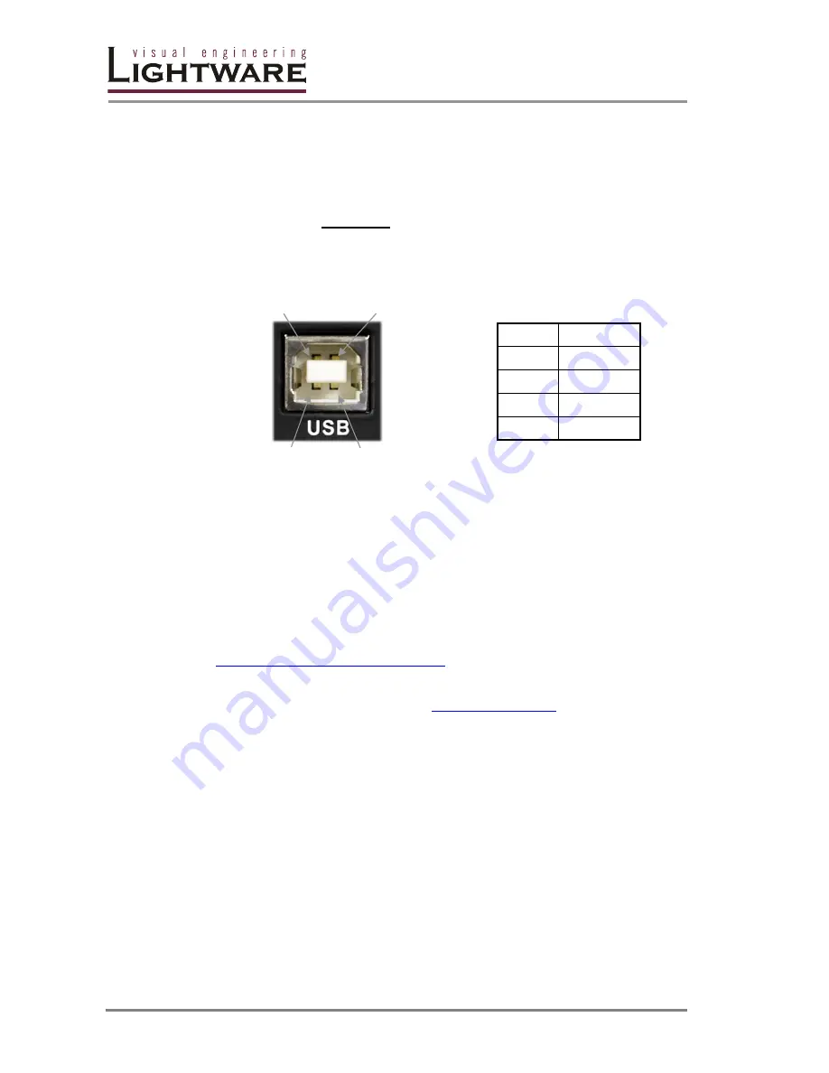
1.8.2. USB control port
DA2DVI-Pro can be remote controlled via a commonly used USB connector
located on the rear panel of the unit. Connect a USB Type A/B cable between the
DA2DVI-Pro and the controlling PC or laptop.
Please make sure
not to send
any commands to the DA2DVI-Pro via the USB port
until it has finished the booting process (EDID Status LED continuously illuminated
green or red). Doing so may result in faulty behavior, in which case please restart
the DA2DVI-Pro.
Pin 2
Pin 1
Pin 3
Pin 4
Pin nr.
Signal
1
+5V
2
Data-
3
Data+
4
GND
USB Type B port pin locations
Table3. – USB Type B pin connections
After connecting the DA2DVI-Pro to the control PC or laptop, the driver of the
device starts installing itself. Normally this is an automatic process. The driver
creates a virtual COM port in the operating system. When running the Lightware
Matrix Controller software, this COM port will be seen in the Available Serial Ports
list.
If the DA2DVI-Pro does not install its driver automatically, please visit the following
website and download the VCP (Virtual COM Port) driver for your operating system
and install it.
http://www.ftdichip.com/Drivers/VCP.htm
For further assistance, please contact
Summary of Contents for DA2DVI-Pro
Page 1: ...DA2DVI Pro User s Manual ...
Page 2: ...Page 2 43 ...
Page 38: ...Page 38 43 7 Mechanical Drawings 7 1 Front view 42 mm 110 mm 7 2 Rear view 42 mm 110 mm ...
Page 39: ...DA2DVI Pro User s Manual Rev 1 3 Page 39 43 7 3 Top view 180 mm 110 mm ...
Page 43: ...DA2DVI Pro User s Manual Rev 1 3 Page 43 43 NOTES ...


