background image

53

1. Overview

2. Setup & Use

3. Optional 


Accessories

4. T

roubleshooting

5. W

arranty

, Safety 


& Specifications

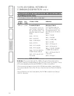
14. RS-232 SERIAL INTERFACE  
COMMAND DEFINITION 

CONT’D

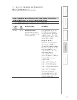
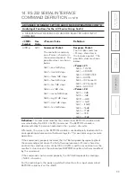
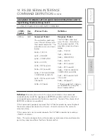
Definition: 

This command modifies the volume-level EEPROM variable which 

was selected by the AICH (<0x90>) command.  The EEPROM variable is 
decremented by the amount indicated in the <param> character.

Afterwards, the value in the EEPROM variable is unconditionally loaded into the 
corresponding volume control hardware register.  This overrides any prior mute 
operation.

If the command is properly received, the CAT 860 responds by repeating back 
the command packet where the first of two replacement <Param> characters 
contains the selection status set by AICH (<0x90>) and the second contains the 
resultant value stored in the volume-level EEPROM variable which was modified 
by this command.

If the command is not received properly, the CAT 860 responds by sending a 
<NACK> character.

For the audio inputs, the power up default values for all six input volume-level 
EEPROM variables is set for -40dB.

<CMD> 

Symbol

Hex 

Value

<Param> Value

Definition

AIDD p

0x93

Command Packet:

The controller sends only 
one <Param> character in 
the command packet.  The 
possible values are shown 
below:

0x81 = one 1dB step

0x82 = two 1dB steps

0x83 = three 1dB steps

0x84 = four 1dB steps

0x85 = five 1dB steps

0x86 = six 1dB step

0x87 = seven 1dB steps

0x88 = eight 1dB steps

0x89 = nine 1dB steps

0x8A = ten 1dB steps

Response Packet:

The CAT 860 sends two 

<Param> characters in 

the response packet.  The 

possible values are shown 

below:

<Param> #1:

0x80 = TV/VCR
0x81 = CD/DVD
0x82 = COMPUTER
0x83 = AUX IN
0x84 = IR Channel A
0x85 = IR Channel B
0x86 = AUX OUT

<Param> #2:

0xCF = 0 dB
0xCE = -1dB
0xCD = -2dB
0xCC = -3dB
0xA7 = -40dB
0x83 = -76dB
0x82 = -77dB
0x81 = -78B
0x80 = -79dB

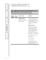
ADVANCED COMMAND SET FOR AUDIO MIXER OPERATIONS CONT’D
Audio Input Functions for the A/V Source Group Cont’d

2. DIFFERENTIALLY DECREASE VOLUME FOR SELECTED AUDIO INPUT  
COMMAND

Summary of Contents for CAT 860

Page 1: ...U s e r M a n u a l Classroom Audio System 860 CAT 860 ...

Page 2: ......

Page 3: ...eaker Connection s 22 Step 5D Audio Input Connections 23 Step 6 Audio Integration 24 Step 7 Charging the REDMIKE 25 Step 8 Set up and Operation of REDMIKE 26 9 Audio Equalization of the CAT 860 27 10 Output to Personal Assistive Listening Device 28 11 Using the REDMIKE to Amplify External Audio Equipment 29 12 PageFirst Priority Mute 30 13 RS 232 Serial Interface Programming 30 Serial Interface Pr...

Page 4: ...eo Source Command 46 12 Query Absolute Volume Audio Video Source Command 47 13 Query Absolute Volume Microphone Audio Input Command 48 14 Query Mute for Audio Video Source Command 49 15 Query Mute for Microphone Audio Inputs Command Advanced Command Set for Audio Mixer Operations Audio Input Functions for the A V Source Group 50 1 Select Audio Input Command 51 2 Query Selected Audio Input Command ...

Page 5: ...ctions Group 68 1 Query Model and Software Version Command SECTION 3 71 REDMIKE VC Controls and Connections Optional Accessories 72 Charging 72 Initial Set Up 73 LT 71 Controls and Connections 74 Charging 75 Initial Set Up 76 REDMIKE Share Controls and Connections 77 Charging 78 Initial Set Up 79 iR Media Connector Initial Setup 80 Audio Integration 80 Other Optional Accessories SECTION 4 81 Troub...

Page 6: ... walked on or pinched particularly at plugs convenience receptacles and the point where they exit from the apparatus 11 Only use attachments accessories specified by the manufacturer 12 Use only with a cart stand tripod bracket or table specified by the manufacturer or sold with the apparatus When a cart is used use caution when moving the cart apparatus combination to avoid injury from tip over 1...

Page 7: ......

Page 8: ...ecifications 2 Setup Use Amplifier Power Supply SECTION 1 OVERVIEW SYSTEM COMPONENTS AND UNPACKING The standard configuration of the CAT 860 will contain ISR Infrared Sensor Receiver and Cable Charging Cradle and Power Supply REDMIKE Classroom Microphone CAT 860 Amplifier 860 ...

Page 9: ...fier mixer PS 24V 2 5 24V 2 5A power supply for CAT 860 RX ISR Infrared sensor receiver with mounting bracket CA PSE50 50 plenum rated Cat 5e cable RMT REDMIKE classroom microphone with battery BA NH2A27 AA NiMH rechargeable sensing battery for REDMIKE AC RMLC2 REDMIKE lavaliere cord BC RMCC REDMIKE cradle charger PS 5V 1 0 5V 1 0A power supply for cradle charger SPEAKERS Contact Lightspeed at 800...

Page 10: ...e REDMIKE Share Handheld Mic Charger Cable LT 71 LT 71 LightMic and Charger Cable Optional Components RMV REDMIKE VC microphone with battery RMS REDMIKE Share handheld microphone with battery pack LT71 LightMic microphone with batteries BA NH2A27 AA NiMH rechargeable sensing battery for REDMIKE BA NH2APK NiMH rechargeable battery pack for REDMIKE Share BA NH1 AA NiMH rechargeable battery for LT71 ...

Page 11: ...3 A VOLUME Controls the volume of the teacher microphone set to channel A 4 B VOLUME Controls the volume of the student or second teacher microphone set to channel B 5 AUDIO INPUT VOLUMES Control the volume of the audio coming from the media source computer TV VCR CD DVD etc connected to the corresponding input on the rear panel 6 ALD OUTPUT AND VOLUME This jack sends mixed audio to external equip...

Page 12: ...the REDMIKE cradle charger 5 DC POWER Plug the 24 V power supply into this jack 6 PAGING INPUT AND ADJ Connect the input from optional PageFirst sensor here when interface with a buildings paging system Use the ADJ control to adjust the sensitivity if needed 7 EQUALIZER 4 BAND Adjust these controls upon installation to properly equalize the system to produce optimium audio quality from the microph...

Page 13: ... These lights glow when the corresponding microphone set to channel A or B is turned on and transmitting A steady light indicates a strong signal 3 SENSOR OUT Connect the CAT 5 sensor cable to this connection to send audio from the microphones to the CAT 860 amplifier 4 IR EXPANSION Connect up to three passive IR sensors IR SR70F to this connection for larger classrooms For more than one additiona...

Page 14: ...osable protective tab before use NOTE do not attempt to remove the tab without first opening the compartment door as it may tear leaving fragments 5 AUDIO MICROPHONE INPUT Use this input to plug in a laptop MP3 player or other audio source to wirelessly transmit audio to be played through the system Alternatively an external microphone can be connected 6 CHANNEL SELECT SWITCH CH A B This switch al...

Page 15: ... light indicates that no battery is sensed REDMIKE Yellow Protective Tab may not have been completely removed see page 10 item 4 A blinking Green LED means a non Lightspeed battery has been installed possibly an alkaline battery 2 DC POWER PORT Connect the DC power cord here 3 OPTIONAL CHARGING PORT Plug the charging cord for the optional LT 71 or the REDMIKE Share microphones here CRADLE CHARGER ...

Page 16: ...ion near the other equipment to be used It can be set in a cabinet on a tabletop or mounted on the wall with the included bracket Media Cabinet Set up The included wall bracket is specifically designed to support the CAT 860 Wall mount Set up SECTION 2 SET UP USE 1 LOCATION OF THE AMPLIFIER Avoid Separated Set ups Components should be housed together Wires should be routed back directly to the amp...

Page 17: ...lassroom Audio System The ISR should be as high as possible in the room the ceiling is the best location centered along the longest wall in the room When possible use a conduit to protect the wires not included Poor choices for placement are corners on walls at heights lower than 7 feet 2 meters or in places where the line of sight from the ISR to the receiver is or could be obstructed Good placem...

Page 18: ...with one corner b Attach the second tab around the other side of the t bar c Repeat with the other side of the bracket so it is connected at all four points 2 Slide the ISR onto the bracket until it clicks into place a Guide the mounting rails onto the bracket oriented as pictured b Once secure the ISR locks into place c To remove the ISR press the release bar down and slide the ISR off the bracke...

Page 19: ...0 amplifier securing it along with way using surface raceway where possible 3 Slide the ISR onto the bracket until it clicks into place 2 IR SENSOR RECEIVER ISR INSTALLATION CONT D Wall Solid Ceiling Mount a Guide the mounting rails onto the bracket oriented as pictured b Once secure the ISR locks into place c To remove the ISR slide a ruler or screwdriver behind the ISR to press the release bar d...

Page 20: ...ight should allow for access to front control panel but also be in compliance with building and ADA regulations B Screw the bracket to the wall at the two screw hole points with the included hardware Attach to a stud when possible use the drywall mollies when studs are not available C Slide the CAT 860 onto the bracket using the channel on the bottom of the amplifier D Secure the CAT 860 to the br...

Page 21: ... to the CAT 860 Ensure the sensor cable is securely attached and locked into place 1 Ensure the power button is depressed in the OFF position 2 Connect the CD end of the power supply to the black power jack labeled DC POWER 3 Connect the black AC power cable from the power supply to a wall outlet RS 232 IN Front Panel RS 232 Control Select 1 2 CAT 860 Amplifier DC Power Source Cable ISR Sensor Rec...

Page 22: ...ol Select 1 2 5C SPEAKER CONNECTION S 5D AUDIO INPUT CONNECTIONS Next connect the CAT 860 to the speakers Then be sure any auxiliary audio sources are connected to the corresponding labeled input on the CAT 860 1 Ensure speaker wire connections are secure and not frayed Note Wiring to these terminals should follow the Class 2 wiring methods as outlined in the National Electric Code ...

Page 23: ...ate TV VCR CD DVD or computer directly into the CAT 860 1 7 3 4 5 6 2 1 PROJECTOR 2 LAPTOP 3 CAT 860 4 DVD 5 ISR SENSOR 6 TEACHER S MICROPHONE 7 SPEAKERS 1 Ensure the power is switched off and the audio input volume controls are turned all the way down 2 Connect the appropriate RCA or 3 5mm audio cable not included from the audio source into the corresponding input jack on the rear panel of the CA...

Page 24: ...eached A blinking light indicates a charging or sensing error See Troubleshooting section for more information REDMIKE incorporates alkaline protection into the microphone design Always use a Lightspeed rechargeable sensing battery Replacement AA NiMH batteries may only be purchased through Lightspeed Technologies part BA NH2A27 Do not attempt to charge alkaline batteries They can overheat and exp...

Page 25: ...t 4 While speaking in a normal voice slowly increase the volume of the corresponding channel on the CAT 860 until your voice is barely audible Each REDMIKE has its channel pre set to either A or B as indicated on the back of the Mic REMEMBER This equipment supplements the user s voice so they are able to speak in a conversational tone Having the volume set too high will result in feedback and list...

Page 26: ...ack is still present with the audio set at the right level make the following EQ adjustments High pitched ring lower the 2K and or 4K adjustment by _ turn Lower pitched ring lower the 500 and or 1K adjustment by _ turn If you notice the sound is muddy or has too much bass Lower the 500 adjustment by _ turn and or Raise the 2K or 4K adjustment by 1 8 turn Note the EQ adjustments should be preset at...

Page 27: ... a 3 5 mm to 3 5 mm patch cable part CA MMC3535 not included 3 Connect a patch cable from the ALD s microphone jack or AUX input to one of the following 3 5mm audio jack on the CAT 860 ALD OUT on the front panel AUX OUT on the back panel 4 Adjust the volume control on the ALD s receiver to maximum output NOTE This is to set the maximum allowable signal from the CAT 860 5 With the CAT 860 and ALD t...

Page 28: ...e to amplify the external audio equipment so the teacher s volume on the Channel A teacher mike does not have to be adjusted To determine which REDMIKE is set to Channel B you can look at the switch on the back of the mike or speak into one of the mics and watch which set of LED s glow on the front panel of the CAT 860 A Volume or B Volume correspond to Channels A or B 1 Plug your external audio e...

Page 29: ...hool wide messages are never missed How it works 1 PageFirst sensor clip is hung around the lead wires attached to the classroom paging speaker 2 The clip is hard wired to the CAT 860 3 As a page is broadcast the sensor clip detects the audio signal through induction and immediately mutes the CAT 860 4 When the page is over the audio from the CAT 860 returns to normal volume level For full install...

Page 30: ...el serially along the RS 232 signal link between the external controller and the CAT 860 The command and parameter information is in the form of two hexadecimal values contained in the 8 data bits of each RS 232 character The above graphic illustrates a typical RS 232 logic waveform representing a character Data format 1 Start bit 8 Data bits No Parity 1 Stop bit The data transmission starts with ...

Page 31: ...cted to a subset of the Basic Command Set These controllers usually cannot utilize the query commands or the response packets More capable high end serial controllers can take advantage of the complete features of the Basic Command Set The Advanced Command Set treats the CAT 860 as an audio mixer which is aligned with the traditional usage for Lightspeed CAT 800 series products The Advanced Comman...

Page 32: ...rce Inputs 3 Action Command Functions for the Advanced Command Set Audio Mixer Operations a Select Control of Microphone Input Channel A or B b Set Differential Microphone Input Channel Volume c Set Absolute Microphone Input Channel Volume d Select Control of Audio Video Source TV VCR CD DVD COMP or AUX e Set Differential Audio Video Source Volume f Set Absolute Audio Video Source Volume g Select ...

Page 33: ...mand packets do not have a Param character but all response packets will have one or two Param characters Example CMD Param Param EOT Example STX CMD Param EOT c The Query Command response is for the most part the query command repeated back to the serial controller However the response packet also includes one or two imbedded Param characters which contain the values of the pertinent CAT 860 regi...

Page 34: ... not receive an end character after waiting 50ms after receiving valid start and command characters CMD find hex value from Table 1 This is the general symbol for the command character derived from Table 1 Param find hex value from Table 1 This is the general symbol for the parameter character s associated with the command character They are derived form Table 1 13 RS 232 SERIAL INTERFACE PROGRAMM...

Page 35: ...roller STX CMD EOT CAT 860 STX CMD Param Param EOT General Format for Aborted Command Exchange Both Basic and Advanced Command Sets In this example the external controller sends either an action or query command to CAT 860 and the command is either corrupted or unsupported The Param characters can be absent Controller STX CMD Param EOT CAT 860 NACK Note It is expected that each button press from t...

Page 36: ...ports will be muted by sending the 79dB setting their corresponding volume control hardware registers Note that muting inputs does not change the values in any of the volume level EEPROM variables Response Packet If the command is properly received the CAT 860 responds by repeating back the command packet to the serial controller If the command is not received properly the CAT 860 responds by send...

Page 37: ...hree unselected audio video source inputs remain muted Response Packet If the command is properly received the CAT 860 responds by repeating back the command packet to the serial controller with an added imbedded Param character containing the value loaded If the command is not received properly the CAT 860 responds by sending a NACK character 14 RS 232 SERIAL INTERFACE COMMAND DEFINITION CONT D B...

Page 38: ...by 2 dB This overrides any previous mute commands The remaining three unselected audio video source inputs remain muted Response Packet If the command is properly received the CAT 860 responds by repeating back the command packet with an added imbedded Param character containing the value loaded If the command is not received properly the CAT 860 responds by sending a NACK character BASIC COMMAND ...

Page 39: ...he CAT 860 responds by sending a NACK character DMAI 0xE4 Command Packet The controller sends no Param character in the command packet Decrement the volume of the microphone channel A and B audio by 2 dB This overrides any previous mute commands Response Packet If the command is properly received the CAT 860 responds by repeating back the command packet with an added imbedded Param character conta...

Page 40: ... Response Packet If the command is properly received the CAT 860 responds by repeating back the command packet with an added imbedded Param character containing the value 0x81 indicating that the A V audio sources are in the muted state If the command is not received properly the CAT 860 responds by sending a NACK character 14 RS 232 SERIAL INTERFACE COMMAND DEFINITION CONT D BASIC COMMAND SET FOR...

Page 41: ...d None of the input volume level EEPROM variables are modified Response Packet If the command is properly received the CAT 860 responds by repeating back the command packet with an added imbedded Param character containing the value 0x80 indicating that the A V audio sources are no longer in the muted state If the command is not received properly the CAT 860 responds by sending a NACK character 14...

Page 42: ...sponds by sending a NACK character 8 UN MUTE MICROPHONE AUDIO INPUTS COMMAND UMAI 0xE8 Command Packet The controller sends no Param character in the command packet Definition The un mute microphone volume command reloads the previously set microphone volume levels Response Packet If the command is properly received the CAT 860 responds by repeating back the command packet with an added imbedded Pa...

Page 43: ...t The Toggle Mute command toggles between mute and un mute for the audio video source inputs When set to mute the 860 Aux Audio Inputs are set to 79dB When set to unmute the 860 resets the previously selected input to it s previous volume setting and the remaining three Aux Audio Inputs remain set at 79dB Response Packet If the command is properly received the CAT 860 responds by repeating back th...

Page 44: ... character in the command packet This command toggles between mute and un mute for the microphone audio inputs When set to mute the 860 microphone Channel A B volumes are set to 79dB When set to unmute the 860 resets the microphone volumes to their previous volume setting Response Packet If the command is properly received the CAT 860 responds by repeating back the command packet with an added imb...

Page 45: ... by EAVS 0xE0 Response Packet If the command is properly received the CAT 860 responds by repeating back the command packet to the serial controller with the added Param character containing the value indicating the enable status set by EAVS 0xE0 The possible values are shown below 0x80 TV VCR Enabled 0x81 CD DVD Enabled 0x82 COMPUTER Enabled 0x83 AUX IN Enabled If the command is not received prop...

Page 46: ...lume level for the audio video sources inputs Response Packet If the command is properly received the CAT 860 responds by repeating back the command packet to the serial controller with the added Param character containing the absolute volume level for the audio video sources The possible values are shown below 0xCF 0 dB 0xCE 1dB 0xCD 2dB 0xCC 3dB 0xA7 40dB If the command is not received properly ...

Page 47: ...crophone audio inputs Response Packet If the command is properly received the CAT 860 responds by repeating back the command packet to the serial controller with the added Param character containing the absolute volume level for the audio video sources The possible values are shown below 0xCF 0 dB 0xCE 1dB 0xCD 2dB 0xCC 3dB 0xA7 40dB 0x83 76dB 0x82 77dB 0x81 78B 0x80 79dB If the command is not rec...

Page 48: ...er contains the mute state for the audio video sources Response Packet If the command is properly received the CAT 860 responds by repeating back the command packet with an added imbedded Param character containing the value 0x80 if the state is un muted and 0x81 if the state is muted The possible values are shown below 0x80 Un muted 0x81 Muted If the command is not received properly the CAT 860 r...

Page 49: ...ontains the mute state for the microphone audio inputs Response Packet If the command is properly received the CAT 860 responds by repeating back the command packet with an added imbedded Param character containing the value 0x80 if the state is un muted and 0x81 if the state is muted The possible values are shown below 0x80 Un muted 0x81 Muted If the command is not received properly the CAT 860 r...

Page 50: ...5 commands That is multiple commands will be able to independently affect the values of the same volume level EEPROM variables which correspond to the IR CH A the IR CH B and the AUX OUT This is true even if the two commands have been directed to the same volume level EEPROM variable In this case the EEPROM variable retains the value from the last command issued from the serial controller CMD Symb...

Page 51: ...ry response packet where the Param contains the selection status set by AICH 0x90 If the command is not received properly the CAT 860 responds by sending a NACK character Response Packet The CAT 860 sends only one Param character in the response packet The possible values are shown below 0x80 TV VCR 0x81 CD DVD 0x82 COMPUTER 0x83 AUX IN 0x84 IR Channel A 0x85 IR Channel B 0x86 AUX OUT ADVANCED COM...

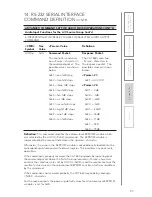
Page 52: ...nd is not received properly the CAT 860 responds by sending a NACK character For the audio inputs the power up default values for all six input volume level EEPROM variables is set for 40dB CMD Symbol Hex Value Param Value Definition AIDI p 0x92 Command Packet The controller sends only one Param character in the command packet The possible values are shown below 0x81 one 1dB step 0x82 two 1dB step...

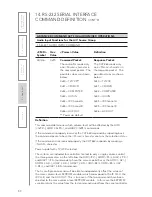
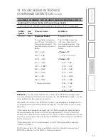
Page 53: ...not received properly the CAT 860 responds by sending a NACK character For the audio inputs the power up default values for all six input volume level EEPROM variables is set for 40dB CMD Symbol Hex Value Param Value Definition AIDD p 0x93 Command Packet The controller sends only one Param character in the command packet The possible values are shown below 0x81 one 1dB step 0x82 two 1dB steps 0x83...

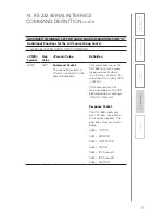
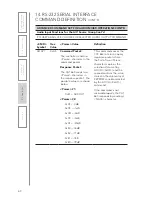
Page 54: ... was modified by this command If the command is not received properly the CAT 860 responds by sending a NACK character For the audio inputs the power up default values for all six input volume level EEPROM variables is set for 40dB CMD Symbol Hex Value Param Value Definition AIAV p 0x94 Command Packet The controller sends only one Param character in the command packet The possible values are shown...

Page 55: ...erly the CAT 860 responds by sending a NACK character CMD Symbol Hex Value Param Value Definition AIAV 0x95 Command Packet The controller sends no Param character in the command packet Response Packet The CAT 860 sends two Param characters in the response packet The possible values are shown below Param 1 0x80 TV VCR 0x81 CD DVD 0x82 COMPUTER 0x83 AUX IN 0x84 IR Channel A 0x85 IR Channel B 0x86 AU...

Page 56: ...y received the CAT 860 responds by repeating back the command packet where the Param character contains the selection status If the command is not received properly the CAT 860 responds by sending a NACK character Power up default is AUX selected QUERY SELECTED AUDIO OUTPUT COMMAND AOCH 0xA1 Command Packet The controller sends no Param character in the command packet Response Packet The CAT 860 se...

Page 57: ...e level EEPROM variable which was selected by the AOCH 0xA0 command The EEPROM variable is incremented by the amount indicated in the param character Afterwards the value in the EEPROM variable is unconditionally loaded into the corresponding volume control hardware register This overrides any prior mute operation If the command is properly received the CAT 860 responds by repeating back the comma...

Page 58: ...M variable which was selected by the AOCH 0xA0 command The EEPROM variable is decremented by the amount indicated in the param character Afterwards the value in the EEPROM variable is unconditionally loaded into the corresponding volume control hardware register This overrides any prior mute operation If the command is properly received the CAT 860 responds by repeating back the command packet whe...

Page 59: ...e AOCH 0xA0 command The EEPROM variable is set the value indicated in the param character Afterwards the value in the EEPROM variable is unconditionally loaded into the corresponding volume control hardware register This overrides any prior mute operation If the command is properly received the CAT 860 responds by repeating back the command packet where the first of two replacement Param character...

Page 60: ... 40dB 0x83 76dB 0x82 77dB 0x81 78B 0x80 79dB This command causes the CAT 860 to return a query response packet where the first of two Param characters contains the selection status set by AOCH 0xA0 and the second contains the value stored in the volume level EEPROM variable selected by the AOCH 0xA0 command If the command is not received properly the CAT 860 responds by sending a NACK character 14...

Page 61: ...erly received the CAT 860 responds by repeating back the command packet where the Param contains the selection status If the command is not received properly the CAT 860 responds by sending a NACK character Power up default is IR Channel A selected QUERY SELECTED INFRARED INPUT COMMAND IICH 0xB1 Command Packet The controller sends no Param character in the command packet Response Packet The CAT 86...

Page 62: ...lume level EEPROM variable which was selected by the IICH 0xB0 command The EEPROM variable is incremented by the amount indicated in the Param character Afterwards the value in the EEPROM variable is unconditionally loaded into the corresponding volume control hardware register This overrides any prior mute operation If the command is properly received the CAT 860 responds by repeating back the co...

Page 63: ...lume level EEPROM variable which was selected by the IICH 0xB0 command The EEPROM variable is decremented by the amount indicated in the param character Afterwards the value in the EEPROM variable is unconditionally loaded into the corresponding volume control hardware register This overrides any prior mute operation If the command is properly received the CAT 860 responds by repeating back the co...

Page 64: ... selected by the IICH 0xB0 command The EEPROM variable is set the value indicated in the param character Afterwards the value in the EEPROM variable is unconditionally loaded into the corresponding volume control hardware register This overrides any prior mute operation If the command is properly received the CAT 860 responds by repeating back the command packet where the first of two replacement ...

Page 65: ...A7 40dB 0x83 76dB 0x82 77dB 0x81 78B 0x80 79dB 14 RS 232 SERIAL INTERFACE COMMAND DEFINITION CONT D Definition This command causes the CAT 860 to return a query response packet where the first of two Param characters contains the selection status set by IICH 0xB0 and the second contains the value stored in the volume level EEPROM variable selected by the IICH 0xB0 command If the command is not rec...

Page 66: ... The possible values are shown below 0x80 TV VCR 0x81 CD DVD 0x82 COMPUTER 0x83 AUX IN 0x84 IR Channel A 0x85 IR Channel B 0x86 TV VCR CD DVD COMPUTER AUX IN 0x87 IR Channel A IR Channel B 0x88 All Inputs Definition This command sends the 79dB setting into the volume control hardware register s corresponding to the value in the param character None of the corresponding volume level EEPROM variable...

Page 67: ...el A IR Channel B 0x88 All Inputs Power up default and may be needed after using the Basic Command Set 14 RS 232 SERIAL INTERFACE COMMAND DEFINITION CONT D Definition Based on the value in the param character this command unconditionally sends the appropriate EEPROM variable content s into the corresponding volume control hardware register s None of the volume level EEPROM variables are modified I...

Page 68: ...en param characters Each param value represents one ASCII character of a string indicating the product model and software version If the command is not received properly the CAT 860 responds by sending a NACK character PING CAT 860 COMMAND PING 0xC1 Controller sends no param value This command causes the CAT 860 to respond with ACK only If the command is not received properly the CAT 860 responds ...

Page 69: ...A ten 1dB steps Differentially decrease volume for selected audio input channel CAT 860 responds with ACK only AIAV p 0x94 Controller sends only one param per CMD 0xCF 0 dB 0xCE 1dB 0xCD 2dB 0xCC 3dB 0x83 76dB 0x82 77dB 0x81 78B 0x80 79dB These are the values returned in the Param character of a query response from the 860iR Set absolute volume for selected audio input channel CAT 860 responds wit...

Page 70: ...efinition Audio Input Functions MREV 0xC0 Controller sends no param value Query model and software version Param string in response packet will be composed of up to sixteen ACSII alphanumeric characters PING 0XC1 Controller sends no param value Ping CAT 860iR CAT 860 responds with ACK only 13 RS 232 SERIAL INTERFACE PROGRAMMING CONT D ...

Page 71: ...uld only be replaced by a Lightspeed AA rechargeable sensing battery part BA NH2A27 4 YELLOW PROTECTIVE TAB Slide the battery compartment door and remove this disposable protective tab before use 5 AUDIO MICROPHONE INPUT Use this input to plug in a laptop MP3 player or other audio source to wirelessly transmit audio to be played through the system Alternatively an external microphone can be connec...

Page 72: ...me instructions for the REDMIKE See page 17 and follow the same instructions for the REDMIKE to setup the REDMIKE VC NOTE A nominal volume level must be set on the CAT 805iX before adjusting controls on the REDMIKE VC The teacher can now use the controls on the REDMIKE VC to adjust the volume level from anywhere in the room The microphone volume control has 4 steps up and 4 steps down from the mid...

Page 73: ...charged A RED light indicates a charge is needed 4 EXTERNAL MICROPHONE INPUT MIC Use the 3 5mm MIC jack for the optional TK 250 headset microphone part MC TK250LTM 5 AUXILIARY AUX Plug a laptop MP3 player or other audio source into this jack to wirelessly transmit the audio signal to be played through the system 6 CHARGER INPUT CHARGER Plug the charging cable from the charger into this jack for da...

Page 74: ...1 and plug the other end into the charging jack on the rear of the REDMIKE cradle charger The LT 71 s rechargeable batteries are factory installed The LED on the front of the LT 71 will glow RED when charging 3 Leave the LT 71 plugged in overnight 8 10 hrs to obtain a full charge NOTE If the system was purchased without a REDMIKE or REDMIKE VC the LT 71 will utilize a charging cable Simply connect...

Page 75: ...ating channel to B 3 Slip the LT 71 with lanyard around the neck and position the top of the microphone just below the collarbone NOTE Positioning of the LT 71 is critical for proper volume adjustment 4 While speaking in a normal voice slowly increase the volume for Channel B on the CAT 860 until your voice is barely audible REMEMBER This equipment supplements the user s voice so they are able to ...

Page 76: ...el When charging the light glows red 3 AUDIO INPUT plug a laptop MP3 player or other audio device into this jack to wirelessly transmit the audio signal to be played through the system 4 CHANNEL SELECT SWITCH CH A B Located in the battery compartment this switch is set to Channel B at the factory 5 CHARGER INPUT Plug the charging cable from the REDMIKE cradle charger or into this jack REDMIKE Shar...

Page 77: ...e is turned OFF 2 Make sure the cradle charger is plugged into a wall outlet Connect one end of the charging cable into the jack labeled CHARGER on the bottom of the REDMIKE Share 3 Plug the other end into the charging jack on the rear of the cradle charger 4 The LED on the microphone will glow RED to indicate charging 5 Leave the REDMIKE Share plugged in overnight 8 10 hours to obtain a full char...

Page 78: ...n the REDMIKE Share by sliding the switch to the top position 3 Grip the barrel in the center section 4 While speaking in a normal voice increase the B VOLUME level until your voice is barely audible REMEMBER This equipment is designed to supplement and distribute the user s voice so they are able to speak in a conversational tone Having the volume set too high will result in feedback and listener...

Page 79: ...olume on the classroom audio system you will also be changing the volume for your second microphone Return the CH B volume knob to the original position before turning the second microphone back on 2 The iR Media Connector volume is preset for most standard audio signals If you need to turn the volume up or down follow this procedure A Adjust the volume at the computer television or other audio so...

Page 80: ...3535 3 5mm to 3 5mm stereo audio cable OPTIONAL IR MEDIA CONNECTOR AUDIO INTEGRATION OTHER OPTIONAL ACCESSORIES The iRMC is designed to integrate with the CAT 860 and multiple audio sources allowing other instructional technologies to be clearly heard throughout the classroom Projector DVD VCR Speaker s IR Sensor iR Media Connector Projector Audio In Audio Out IR Transmission Video In Audio Out Au...

Page 81: ...the microphone to Channel A PROBLEM Low Volume or Feedback SOLUTION Follow these steps to eliminate low volume or feedback Ensure microphone is positioned appropriately just below the collar bone Check volume level on the amplifier If the volume is too high feedback will occur Adjust accordingly Adjust the volume level on the back of the optional REDMIKE VC PROBLEM No Sound From Speaker SOLUTION F...

Page 82: ...ate amplification approximately 5 10 dB above ambient room noises Avoid wearing jewelry that may rub or bump against the microphone Turn the REDMIKE off during private conversations with a student parent or other classroom visitor You can also cover the LED lens on top of the REDMIKE to block the signal Recharge batteries each night When recharged nightly operating time actual usage for the transm...

Page 83: ...nt to the customer to minimize downtime Customers will receive the exchange product s or component s within 2 3 days A prepaid return label will be included with exchanged products so original malfunctioned equipment can be returned to Lightspeed Any exchanged equipment will remain covered under the original five 5 year warranty 1 Warranty on infrared microphones is FIVE 5 YEARS 2 Warranty on Ligh...

Page 84: ......

Page 85: ...EED and 2004 108 EC Electromagnetic Compatibility Directives Lightspeed Technologies launched a formal product recycle program in Europe that complies with the European Union Directive 2002 96 EC on Waste Electrical and Electronic Equipment WEEE Directive Please visit our website at www Lightspeed tek com for more information This product is manufactured using lead free processes and is free of ot...

Page 86: ...Battery Power 1 year warranty 1 AA NiMH Rechargeable Sensing Audio Input 3 5 mm Dimensions W x D x H 0 9 x 1 0 x 3 5 Weight 2 1 oz LT 71 LightMic Audio Distortion 1 Built in Microphone Unidirectional Electret Battery Power 1 year warranty 2 AA NiMH Rechargeable Audio Inputs Mic Level 3 5 mm Line Level 3 5 mm Dimensions W x D x H 1 375 x 75 x 4 625 Weight 3 7 oz REDMIKE Share Handheld Microphone Au...

Page 87: ......

Page 88: ...LIGHTSPEED TECHNOLOGIES 11509 SW HERMAN ROAD TUALATIN OR 97062 TOLL FREE 800 732 8999 PHONE 503 684 5538 FAX 503 684 3197 LIGHTSPEED TEK COM MN0258US01 3 ...

Reviews: