A s s e m b l y S t e p 2
Pivot Tube(See Note)
QM893
Page 7
Note:
Make sure
Left /Rgiht Coupler Bar (104L/104R)
are at the correct side when its horizontal pivot tube, which is
welded at the top, faces the
REAR
of the machine as seen from the user.
B
B
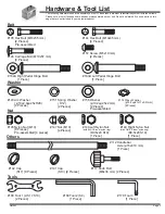
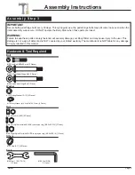
Washer
#156 Washer
(φ10.2xφ25x2 mm)
[2 Pieces]
#145 Nylon Nut (M10)
[2 Pieces]
Others
#112 Handlebar
Axle (φ16x410 mm)
[1 Piece]
#142 Cap
(S17)
[2 Pieces]
Tools
#168 T
ool 1 (2-S17,S19)
[2 Pieces]
Hardware & Tool Required
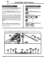
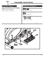
Remove the
Nylon Nuts (#145)
and
Washers (#156)
that
are pre-assembled on the
Handlebar Axle (#112)
and set
them aside as they will be used in a later process.
Insert the
Handlebar Axle (#112)
through the main frame.
Make sure the
Handlebar Axle (#112)
is centered. If you
encounter too much friction, try using WD40 or
Vaseline as
a lubricant.
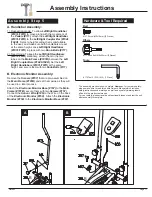
Attach
Left Coupler Bar (#104L)
and
Right Coupler Bar
(#104R)
to the main frame via the
Handlebar Axle (#112)
.
Again, use WD40 or
Vaseline to reduce friction if needed.
Once the
Left Coupler Bar (#104L)
and
Right Coupler
Bar (#104R)
are correctly situated, fasten the end of the
Handlebar Axle (#112)
with a
Washer (#156)
and a
Nylon
Nut (#145)
on each side. Then cap each end with a
Cap
(#142).
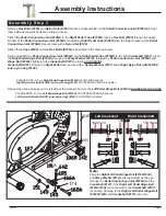
Note:
Make sure
Left/Right Coupler Bar (#104L/#104R)
are at
the correct side when its horizontal Pivot Tube faces the
REAR of the machine as seen from the user. Please refer
to the drawing in below.
55
40
1
2 3
4
55
40
1
2
3
4
STEP3:
Assembly Instructions


