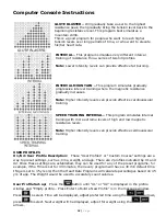
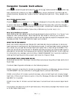
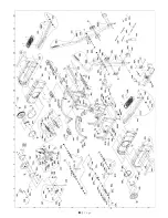
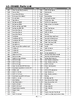
LifeCore Fitness LC-CD600 User'S Product Manual Download Page 30

30


|


P a g e


LC-CD600 Parts List 

Part #  Part Description 

Qty. 

Part #  Part Description 

Qty. 

2872


Green


Ground


Wire


(Computer)


1


2DJ9


M8*1.25

50


Cap


Bolt


3


01HH


Tension


Cable


1


2DL8


Retaining


Clip


2


01HL


Servo


Motor/DC


Motor


1


2DM4


Washer


6


01HR


AC


Adaptor


DC


9v


1000mA


1


2DUW


Retaining


Ring


2


01HU


AC


Inlet


Cable


1


2DZV


Warning


Sticker


Label


2


01J8


Speed


Sensor


1


2E3E


Philips


Screw


Driver


1


0HVQ


Ball


Bearing


6005ZZ


8


2ENV


M3*24

10.


Tapping


Screw


2


0HVX


Ball


Bearing


6203ZZ


4


2GQQ


Rubber


Sleeve


For


Handle


bar


2


0HVY


Belt


Tension


Bearings


6204ZZ


2


2GS0


Collar


1


0HWC


Ball


Bearing


6005Z


NTN


8


2GS1


Pedal


Tube


Bushing


1


0J3P


4mm


Allen


Wrench


1


2H6B


Locker


Support


1


0J3Q


5mm


Allen


Wrench


1


2HG6


M8*1.25

16


Bolt


6


0J3V


6mm


Allen


Wrench


1


2HJB


End


Cap


4


0J4Z


Flat


Washer


4


2HS8


Handrail,


Right


Upper


Frame


1


0J69


Flat


Washer

 φ

6*13

1


12


2HSA


Handrail,


Left


Upper


Frame


1


0J6A


Flat


Washer

 φ

8*16

2.5


16


2HSB


Pedal


Tube


Frame


(Right)


1


0J93


Spring


Washer


2


2HSC


Pedal


Tube


Frame


(Left)


1


0J9C


Spring


Washer


2


2HW8


Computer


Cable


1


0JAF


Green


Ground


Wire


Lock


Washer

 φ

5


1


2HWF


Outlet


1


0JEE


C

RING


A

17


4


2J78


M8*1.25

12


Bolt


24


0JEG


C

RING


A

20


1


2JAW


17mm


Wrench


1


0JEJ


C

RING


A

25


2


2JAW


17mm


Socket


Wrench


1


0K2C


M8X1.25

16


Screw


4


2JN1


Handrail,


Right


Upper


Assembly


1


0K2W


M5*0.8

16


Screw


3


2JN2


Handrail,


Left


Upper


Assembly


1


0K3X


M5X0.8

14


Screw


&


Washer


2


2K2L


Rolling


Wheel


Assembly


2


0K4R


M5*0.8

12


Screw


30


2K54


Heart


Rate


Sensor


Assembly


2


0K7M


M6*1.0

18


Screw


8


2K6R


Heart


Rate


Sensor


End


Cap


2


0KEQ


M5*0.8

12


Screw


2


2LXT


M12*1.75

55


Bolt


2


0KFE


Green


Ground


Wire


M5*0.8

6


Screw


1


2N3N


Center


Shaft


Assembly


2


0KMP


Heart


Rate


Sensor


M3×0.5

2.4


HEX.


NUT


4


2NHZ


C

RING


2


0KNM


M10X1.5


Nut


4


2PHA


M5*0.8

12


Tapping


Screw


22


0KQZ


M10*1.5


T=10


Nut


1


2PVZ


Heart


Rate


Sensor


4


0KR0


M12*1.75


T=12


Nut


6


2PW0


Heart


Rate


Sensor


Holder


4


157W


Heart


Rate


Sensor


M3*0.5

30


Screw


2


2SDP


Bushing


2


20W4


M10*1.5


,


T=6


Nut


2


2UTT


Ball


Bearing


2205


2


21A7


Retaining


Ring


1


2WQA


Upper


Support


Cover


Right


1


21AA


Idler


Wheel


Bracket


1


2WY0


Upper


Support


Cover


Left


1


21B8


M10*1.5

20


Bolt


2


2X70


Shaft


Sleeve


2


21BA


M10*1.5

81.5


Bolt


2


2X71


Arbor


Collar


(A)


2


21BJ


Magnetic


Brake


Assembly


1


2X72


Arbor


Collar


(B)


2


21K5


Magnet


Stand


1


2X7T


Pedal


2


21LG


Collar


2


2X8U


Console


Controller


Circuit


Board


1


21NP


M12*1.75

110


Bolt


2


2X91


Label


Cover/Water


bottle


Holders


Sticker


1


Summary of Contents for LC-CD600

Page 1: ...Core Fitness Inc 2575 Pioneer Ave Suite 101 Vista CA 92081 Serial Number is located on the frame Please send in the attached warranty card Page 33 and a copy of the original receipt or register online...

Page 2: ...2 P a g e...

Page 3: ...re 6 Page 11 Assembly Figure 7 Page 12 Assembly Figure 8 Page 13 Assembly Figure 9 AC Adaptor Location Page 14 Computer Console Instructions Page 15 Monitoring Your Heart Rate Page 22 How To Properly...

Page 4: ...enance tips to keep the product in good working order Make sure that all components are fastened securely including but not limited to pedals handlebars or computer It is recommended the unit be plugg...

Page 5: ...tector Unpack the box in a clear work area to allow smooth assembly Remove all the parts from the packing material however do not discard packing material until assembly is complete Double check packi...

Page 6: ...ly please call LifeCore Fitness at 1 888 815 5553 FIGURE 1 Tools Needed 6mm Allen wrench 0J3V Note It is recommended that two adults help during this step One person holds the upper support tube assem...

Page 7: ...Figure 2 Slide the left side rail into the upper support tube assembly attached the top left side rail using Qty three M6x1 16 bolts and Qty three 6x13 washers Attach the lower portion with Qty three...

Page 8: ...labeled Figure 3 Locate the right and left Handrail Linkage Assemblies See Figure 3 Slide the left handrail linkage assembly on to the lever arm frame Using Qty one 10 2x35 washer Qty one 10 lock wash...

Page 9: ...and align holes Additional help may be needed to help align holes Secure linkage to unit using Qty four M8x1 25 12 hex bolts two on top and two on the bottom Use 6mm Allen wrench to tighten the M8x1...

Page 10: ...assembly to the handrail assembly with Qty one M10x1 5 81 5 hex bolt and Qty one M10x1 5 hex nut Using the 17mm socket wrench and 17mm wrench tighten bolt and nut snug Not Too Tight Please ensure that...

Page 11: ...cate console mast and slide console mast into upper support tube assembly make sure computer cable wire slides down straight and does not get pinched Connect the computer cable wire coming from the co...

Page 12: ...and connect that to the grounding terminal to the left of the 7 pin connector Locate the 3 pin heart rate cable and heart rate ground wires Connect the 3 pin wire to the 3 pin connector on the board...

Page 13: ...6mm Allen wrench 0J3V Locate bag labeled Figure 8 Locate left and right handlebars See Figure 8 Attach left handlebar to handlebar assembly using Qty three M8 16mm hex bolts Using a 6mm Allen wrench...

Page 14: ...nit No other power supply should ever be used to power the machine 14 P a g e Once assembly is complete if needed tighten or loosen the levelers on the bottom of the machine to prevent the machine fro...

Page 15: ...in Calories Pulse Resistance Level and Cal Hour Profile Window Displays program profile tension bar heart rate Bar HR Programs Only lap progress display and lap counter The profile window toggles betw...

Page 16: ...in each of the windows The Console default time will continue to count down until time has reached 0 00 During non heart rate programs the profile window will toggle between the program profile and th...

Page 17: ...s button to confirm Note Default weight is 150 Pounds Weight settings can range from 70 LBS to 330 LBS AGE Once weight has been entered age will show in message window Use the or buttons to select age...

Page 18: ...to select Next weight will be displayed adjust for weight using the arrows GLUTE BLASTER Will gradually take a user to the highest resistance peak then gradually bring the tension level back to the be...

Page 19: ...eart Rate program In all Heart Rate Control programs the console only accepts the wireless heart rate signal from a chest strap transmitter The heart rate hand pulse grips function is disabled during...

Page 20: ...ar workout HR 65 FAT BURN Maintains your Target Heart Rate at 65 of Max Heart Rate by automatically adjusting the tension levels to maintain that percentage This is a good program for people who want...

Page 21: ...ition on the virtual track will blink The tension level will be displayed in the first column Every dot in the tension column will represent an increment of one or two tension levels Tension level goe...

Page 22: ...of exercising the AHA recommends aiming for the lower part of the target heart rate zone 60 then gradually progressing up to 75 According to the AHA exercising above 75 of your maximum heart rate may...

Page 23: ...acemaker or if you are taking medications for a heart condition Medication or electrical pulses from the pacemaker can interfere with accurate heart rate readings Do not bend the chest strips This can...

Page 24: ...ection with your body When you start to sweat the connection may improve 9 Check to see if battery is still working The estimated average battery life of the transmitter is 2000 hours of use If the ba...

Page 25: ...resistance cable and make sure that it is connected to the magnetic flywheel servo motor correctly 9 If the motor is still not changing resistance the computer and or servo motor may need to be replac...

Page 26: ...get a different position 9 If just putting on the chest strap wait a few minutes for the transmitter gets a good connection with your body When you start to sweat the connection will improve 9 Check...

Page 27: ...level with the ground Adjust as needed to level machine 9 If unit is placed on hard surface the machine will need to have a mat placed under the machine to prevent the leveler feet from breaking and t...

Page 28: ...dry towel or use a light house hold cleaner such as Windex to remove dirt The purpose of cleaning the unit is to remove body sweat which contains salt Salt is the number one factor that will cause the...

Page 29: ...2 29 P a g e...

Page 30: ...RING A 17 4 2J78 M8 1 25 12 Bolt 24 0JEG C RING A 20 1 2JAW 17mm Wrench 1 0JEJ C RING A 25 2 2JAW 17mm Socket Wrench 1 0K2C M8X1 25 16 Screw 4 2JN1 Handrail Right Upper Assembly 1 0K2W M5 0 8 16 Screw...

Page 31: ...lt 4 2XLK M6 1 0 50 Screw 6 2CU8 Rolling Wheel 2 2XLS Sticker Rear Cover Upper 1 2CU9 Collar 2 2XLV Program Sticker 1 2D2F Side Cover Right Outside 1 2XLW Heart Rate Sticker 1 2D2G Side Cover Right In...

Page 32: ...Service Notes and History 32 P a g e...

Page 33: ...transportati e Wear items rmal usage L nt improper m nance LifeCo n authorized L riod Your rem usly registered he address be he serial numb er s remaining ranty this prod nsferred warra ime of reques...

Reviews: