


25
|
P a g e
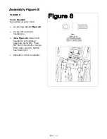
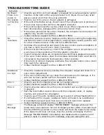
TROUBLESHOOTING GUIDE
Symptom Diagnosis
No Power:
There is no
power to
the console
not turning
on.
9
Check to see if the unit’s AC adaptor is plugged into a surge protector and/or
machine. If the light on the surge protector is lit. Check to see if any other
power sources work from the surge protector.
9
Check to see if the wire on the AC adaptor is damaged.
9
If the unit is first being set up, check to see if the computer wire is pinched, or
if a wire has been pulled out from the plastic connector.
9
If the unit has been used for a while, check to see if the computer wire has not
been disconnected, Unplugged the wire and reconnect them.
9
If the above procedures have been checked, the computer console and/or AC
adaptor may need to be replaced.
9
Contact technical support toll free 1-888-815-5559
No
resistance
9
Check the resistance level by making sure the time is counting then adjusting
and listen for a servo motor adjustment. (winding/motor sound) cycle the unit
for a few minutes and see if the unit has a different feel.
9
Hold down the reset button and check if the servo motor resets and adjusts. If
you hear a motor sound, servo motor is working.
9
If the unit is first being set up, check if the computer wire is not pinched, or if
a wire has not been pulled out from the plastic connector.
9
Check if computer cables are connected and everything is plugged in properly.
9
If the servo motor works, check the resistance cable and make sure that it is
connected to the magnetic flywheel/servo motor correctly.
9
If the motor is still not changing resistance the computer and/or servo motor
may need to be replaced.
9
Contact technical support toll free 1-888-815-555
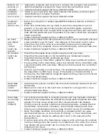
Resistance
too high
9
Check the resistance level by starting the computer. Adjust and listen for a
servo motor adjustment.
9
If the unit is first being set up, check the computer wire for damage, or if a
wire has not been pulled out from the plastic connector.
9
Contact technical support toll free 1-888-815-5559
Error 1
9
Check to see if all computer wires are connected properly.
9
Contact technical support toll free 1-888-815-5559
Error 2
9
Check computer cables insure they are connected and everything is plugged
in properly.
9
Push the reset button several times until the computer resets, or unplug
machine and connect the AC adaptor.
9
Check to see if the units resistance will go to level 16 without flashing Error 2.
9
If unit flashes Error 2 again, resistance motor will need to be recalibrated.
9
If recalibration doesn’t work then servo motor will need to be replaced.
9
Contact technical support toll free 1-888-815-5559
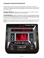
Error
Message
The Message center will display “MOTOR ERROR” message whenever the
brake motor was unable to move to its target position within 2 seconds. Each
time the CD600 is powered on, the console will check the brake motor status.
If the brake motor does not reply, then the console will display the Error
Message “MOTOR ERROR” immediately and disable button operation until
power is reset. To clear this error message, plug and unplug the unit.
Summary of Contents for LC-CD600
Page 2: ...2 P a g e...
Page 29: ...2 29 P a g e...