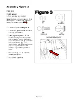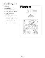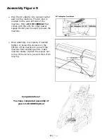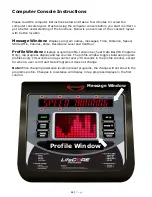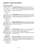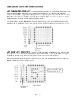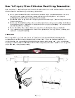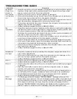
Assembly Figure 7
FIGURE 7
Tools:
Philips Screw driver: 2E3E
Note:
Ensure that all wires are
properly connected inside the
console. Be careful not to pinch the
wires.
¾
Locate bag labeled
Figure 7
.
¾
(See
Figure 7
) Locate console
and connect the 7 pin computer
cable wire into 7 pin connector on
the board. Locate the green
ground wire and connect that to
the grounding terminal to the left
of the 7 pin connector. Locate the
3 pin heart rate cable and heart
rate ground wires. Connect the 3
pin wire to the 3 pin connector on
the board and the black ground
wire to the grounding terminals
next to the 3 pin connector.
¾
Place the computer console on
the console mast. Make sure the
wires fit inside computer and
computer console sits flat on the
console mast.
¾
Grab the Qty. four M5x0.8-12
screws, and using a Philips screw
driver secure console.
Figure
7
12
|
P a g e
Summary of Contents for LC-CD600
Page 2: ...2 P a g e...
Page 29: ...2 29 P a g e...


