background image

Updating the Firmware - Xmodem (Serial) Method

A11

A.6 U

PDATING


THE

 F

IRMWARE

 - X

MODEM

 (S

ERIAL

) M

ETHOD

Follow these steps to update the firmware using the Xmodem (serial) method. This method works 

through the Web card’s serial port, employing terminal emulation software, such as HyperTerminal.

Connect a Cable to the Serial Ports

1. Connect one end of a DB-9 null modem or file transfer cable to the Web card’s serial port and the 

other to the computer’s serial port. 
The correct cable will have, at a minimum, Pins 2 and 3 crossed at the ends, as shown in 

Figure A1

. The configuration cable is available separately from Emerson (P/N LIEBNULL).

Figure A1 Null connection

Open a Terminal Emulation Connection

2. Open a connection to the Liebert IntelliSlot card (if 

needed, see instructions in 

A.2.1 - Open the Terminal 

Emulation Interface - Serial Connection

).

3. Choose 

Firmware Updates 

from the Main Menu.

4. Choose 

XMODEM Update

 from the


Firmware Updates 

menu, seen at right, and enter 

y

 (yes) to confirm your 

choice.

5. Choose 

Xmodem1K

 from the Select Firmware Update 

Protocol, as shown at right.

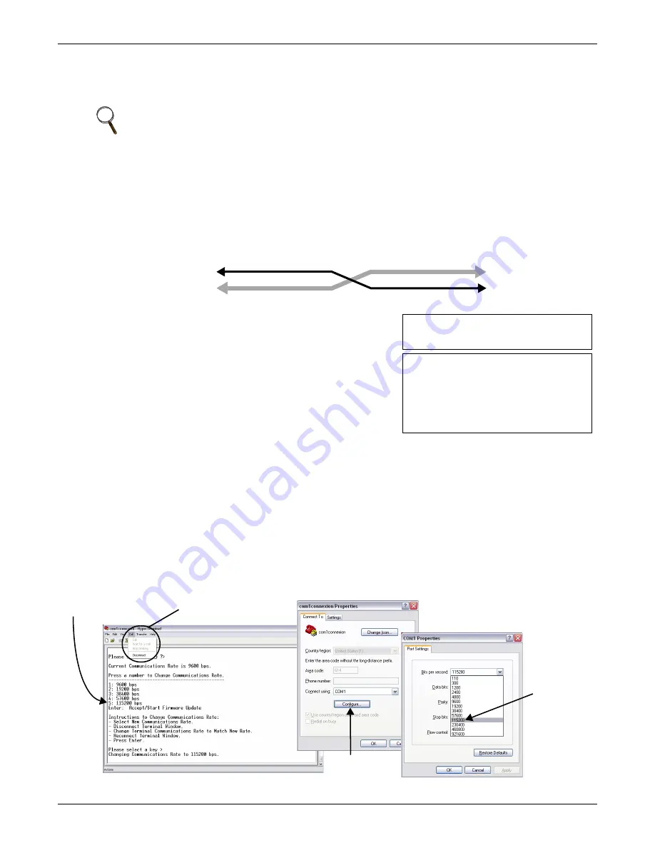
Change the Baud Rate to 115200

6. Choose 

115200 bps

 from the menu, shown below left.

7. From the HyperTerminal menu, click on 

Call

, then choose 

Disconnect

 (this will not close the 

HyperTerminal connection to the card).

8. In the HyperTerminal menu bar, click on 

File

, then choose 

Properties

.

9. Click on the Connect To tab and click the 

Configure

 button. This opens Port Settings tab in the 

COM1 Properties window, as shown below right.

10. Choose 

115200

 from the Bits Per Second drop-down list and click 

OK

, then click 

OK

 to close the 

Properties window.

11. In the HyperTerminal menu bar, click on 

Call

, then choose 

Call

 from the drop-down menu and 

press the Enter key.

NOTE

This method includes a time-sensitive operation requiring expeditious location of the upgrade 

files downloaded in 

A.3.3 - Download the Firmware Upgrade File to the Computer

Read through this entire section before beginning the upgrade.

DTE Device

Receive Rx (Pin 2)

Transmit Tx (Pin 3)

DTE Device

Receive Rx (Pin 2)

Transmit Tx (Pin 3)

Firmware Updates Menu
----------------------
1: XMODEM Update
2: TFTP Update

Firmware Update (Step 1/3)
--------------------------
Select Firmware Update Protocol
-------------------------------
1: XmodemCrc
2: Xmodem1K
x: Exit/Cancel
Please select a key ?>
Current Communications Rate is 9600 bps.

Call menu

Configure 

button

115200 bps

115200 bps

Summary of Contents for IntelliSlot

Page 1: ...IntelliSlot Web Card Liebert IntelliSlot Web Card LB Liebert IntelliSlot Web Card LBDS Liebert IntelliSlot Web Card NXL Liebert IntelliSlot Web Card L Liebert IntelliSlot Web Card IPBML Modbus IP BACn...

Page 2: ......

Page 3: ...3 1 Install a Liebert IntelliSlot Web Card Non Adapter Version 5 3 1 1 Connect the Cable 5 3 1 2 Prepare the Card for Configuration 5 3 2 Install a Liebert IntelliSlot Web 485 Card With Adapter 6 3 2...

Page 4: ...ults Units with IS WEBCARD IS WEBL IS IPBML IS WEBS IS IPBMS IS WEBLB IS WEBNXL Cards Only 35 7 0 MESSAGING 36 7 1 E Mail Configuration 37 7 2 SMS Configuration 38 7 3 Customize Messages 39 8 0 FACTOR...

Page 5: ...nly 50 9 4 3 Events and Parameters Units with IS WEBL IS IPBML IS WEBS IS IPBMS Cards Only 51 10 0 SUPPORT INFORMATION 52 10 1 View Web Card Information 52 10 2 Events and Parameters 53 11 0 BUILDING...

Page 6: ...ings 27 Table 15 Time Server parameters 33 Table 16 Factory default passwords 34 Table 17 Username and password guidelines 34 Table 18 Factory default passwords 35 Table 19 Messaging menu guide 36 Tab...

Page 7: ...G Risk of electric shock Can cause equipment damage injury or death Service and maintenance work must be performed only by properly trained and qualified personnel and in accordance with applicable re...

Page 8: ...ability to many models of Emerson Network Power s line of Liebert UPS power and cooling equipment See Table 1 for equipment supported and Table 2 for communication protocols supported The cards employ...

Page 9: ...iebert Challenger 3000 Liebert Challenger ITR Liebert CW Liebert Deluxe System 3 Liebert DS Liebert PeX Liebert XDC with Liebert iCOM Liebert IntelliSlot Web Card S Liebert IntelliSlot Web Card IPBMS...

Page 10: ...rt Nform Support Utilizing the SNMP and Web technologies built into each of the Liebert IntelliSlot Web cards Liebert Nform will centrally manage alarm notifications to provide you with an easy interf...

Page 11: ...9 port on the card and to a COM port on your PC The configuration cable is available separately from Emerson P N LIEBNULL 2 1 2 Prepare the Card for Configuration Use terminal emulation software such...

Page 12: ...the Modbus application 6 At the next screen select Server ID the default Server ID is 1 but may be any number up to 255 7 Press Esc to return to the Main Menu 8 Select IP Network Settings then Boot IP...

Page 13: ...for example HyperTerminal Configuration Serial Cable or TCP IP Telnet Use a command prompt enter telnet and the IP address or hostname Configuration TCP IP Web Use a Web browser for example Microsoft...

Page 14: ...ttings shown in Table 7 5 When the message at right appears in the HyperTerminal window press the Enter key 6 In the Main Menu enter the number that corresponds to your choice Refer to 3 1 Guide to Co...

Page 15: ...perTerminal window press the Enter key 5 Enter the Administrator username and password both are case sensitive a Login username default is Liebert b Password default is Liebert 6 In the Main Menu ente...

Page 16: ...Login username default is Liebert b Password default is Liebert 4 In the Main Menu enter the number that corresponds to your choice Refer to 3 1 Guide to Configuration for details on each function 5 A...

Page 17: ...nnect To box opens 4 Enter the Administrator username and password both case sensitive a User Name default is Liebert b Password default is Liebert 5 Click OK 6 Refer to 3 1 Guide to Configuration for...

Page 18: ...y a message that the process was successful Web Interface After making each change click the Save button A reminder appears each time you make a change shown at right Without leaving the Configure tab...

Page 19: ...n the right panel After making changes click Save NOTE This information also configures the SNMP parameters sysName sysContact sysDescr and sysLocation available using RFC 1213 MIB II Table 8 Equipmen...

Page 20: ...TP Menu page 33 5 7 Change Username Password Administrator and General User page 34 5 8 Reset WEB Authentication to Factory Defaults Units with IS WEBCARD IS WEBL IS IPBML IS WEBS IS IPBMS IS WEBLB IS...

Page 21: ...eb card to be a network ready device Static Fixed network addresses and other parameters DHCP Central management using dynamic network addresses BootP Older mechanism for central management of network...

Page 22: ...ver settings Parameter Description Valid Settings DNS Mode Obtain DNS server addresses automatically or use specified addresses Note Automatic assignment option is available only if a DHCP server is u...

Page 23: ...interface Click on the Configure tab then Test in the left panel under DNS in the Network Settings group Choose the Type of DNS from the drop down list Hostname Fully Qualified Domain Name or IP Addre...

Page 24: ...lnet Menus SNMP Protocol Enable or disable SNMPv1 v2c or SNMPv3 for remote management SNMP Communications The SNMP Communications Menu shown at right allows you to set up access privileges and configu...

Page 25: ...p Enables system traps to be sent per the LGP MIB The parent option must be also enabled for this to be enabled Heartbeat Trap Interval Specifies how often a heartbeat trap will be sent to show that t...

Page 26: ...Note the options vary according to the type of equipment RFC 1628 MIB features are available for UPS Power equipment only not for Precision Cooling and other equipment as shown at bottom in the exampl...

Page 27: ...tname of the device to be added then press Enter Enter 1 for read or 2 for write access for this device then press Enter Enter the community string then press Enter Example a 10 0 0 5 write public1 th...

Page 28: ...ccess under Management Protocol in the left panel and finally Edit in the right panel After making changes click Save NOTE Avoid the following setting it permits access by any host and may pose a secu...

Page 29: ...to add an entry then press Enter Enter the IP address or hostname of the device to be added then press Enter Enter the port number default is 162 then press Enter Enter the community string then press...

Page 30: ...rough the Web interface Click on the Configure tab then Traps or V1 Traps under Management Protocol in the left panel and finally Edit in the right panel After making changes click Save Click on Edit...

Page 31: ...d number of each item to be edited and make changes as needed When finished enter 0 zero to save changes or Esc to exit without saving Example a press Enter Edit a device see example at right Enter e...

Page 32: ...under Management Protocol in the left panel and finally Edit in the right panel After making changes click Save NOTE Avoid the following setting it permits access by any host and may pose a security...

Page 33: ...icate for Internet Explorer Refer to the appro priate section for your version of Internet Explorer 5 4 2 Install Security Certificates Internet Explorer 6 or earlier 5 4 3 Install Security Certificat...

Page 34: ...ty certificate Open Internet Explorer and enter https followed by the IP address or hostname of the Web card for example https 192 168 0 125 in the address bar The following message appears Click the...

Page 35: ...pens Click Next Click on Automatically select the certificate store based on the type of certificate then click Next The final Wizard window appears with a message that the process is complete Click F...

Page 36: ...https 192 168 0 125 in the address bar The following message appears Click on Continue to this website not recommended to open a connection to the Web card Click the Certificate Error box next to the...

Page 37: ...pens Click Next Click on Automatically select the certificate store based on the type of certificate then click Next The final Wizard window appears with a message that the process is complete Click F...

Page 38: ...rom the Main Menu then Telnet Server 2 Choose Telnet Server then specify Enabled to permit Telnet access Disabled to block access via Telnet Web Interface To access Telnet settings through the Web int...

Page 39: ...k Settings in the left panel and finally Edit in the right panel After making changes click Save Table 15 Time Server parameters Parameter Description Telnet Menus SNTP Time Sync Rate This is how ofte...

Page 40: ...he Web interface Click on the Configure tab then Users in the left panel and finally Edit in the right panel After making changes click Save Table 16 Factory default passwords Type of User Factory Def...

Page 41: ...s to the factory defaults 1 Choose IP Network Settings from the Main Menu then Reset WEB Authentication to Factory Defaults 2 Enter y to reset the Administrator and General User usernames and password...

Page 42: ...eb Interface To access Messaging settings through the Web interface Click on the Configure tab then Messaging in the left panel and finally Edit in the right panel After making changes click Save Tabl...

Page 43: ...ddresses must be added individually Changes may be made by entering d to delete an entry or e to edit an entry NOTE To specify multiple recipients of the e mail message in the Web interface use a semi...

Page 44: ...dd an SMS address use the format a 1112223333 abc com Multiple addresses must be added individually Changes may be made by entering d to delete an entry or e to edit an entry NOTE To specify multiple...

Page 45: ...s or hostname The IP Address or Hostname of the Web card 5 1 Boot IP Settings Event Description of the SNMP event 9 0 Support Information Event Date Time The date time when the SNMP event occurred Nam...

Page 46: ...ll user defined settings described in this manual see 3 0 Configuration Overview through 6 0 Messaging Restores DHCP service the factory default replacing a static IP address or hostname if config ure...

Page 47: ...oose Local Node Settings from the Advanced Communication Settings Menu 4 Choose Node ID from the Local Node Settings Menu then use the following guide and Table 23 to make changes If the Liebert unit...

Page 48: ...ction Telnet To specify router settings for these units 1 Choose Factory Settings from the Main Menu 2 Choose Advanced Communication Settings from the Factory Settings Menu 3 Choose Router Settings fr...

Page 49: ...1 Choose Factory Settings from the Main Menu then choose Support Information 2 The Web card information appears as shown in the following example Press the Enter key to return to the previous menu MAC...

Page 50: ...sk Stack Usage 2 The information appears as shown in the example at right Press the Enter key to return to the previous menu Factory Settings Menu 1 Advanced Communication Settings 2 Agent Event Log 3...

Page 51: ...ame contact location and description of the Liebert unit as defined in 4 0 Equipment Information Device Status current status of the Liebert unit and whether any alarms are active if so the most recen...

Page 52: ...m an operation click on a Control Operations category at left then click on the appropri ate button in the right panel The example below shows control operations for two Liebert units Table 24 Control...

Page 53: ...event text Text stating the type of event and how the card reacted Event Log Controls Download Links The Agent Event Log at the top of the page includes two links txt and csv The txt link will downlo...

Page 54: ...ata Logs tab features Units with IS WEBL Cards Only Feature Description For details see Downloads Event logs data logs and other files that may be downloaded from the Liebert unit 8 4 1 Downloads Unit...

Page 55: ...top of the window Click on Downloads in the left panel Downloadable files are listed as hyperlinks in the right panel in three categories Event logs Data logs and Other files Click on a link to open...

Page 56: ...2 The event ID This is the index number given to events since the start of the history 3 The event text Text stating the type of event and how the card reacted Event Log Controls Download Links The A...

Page 57: ...vents and parameters for the Liebert equipment through the Web interface To view this data Click on the Data Logs tab at the top of the window Click on Events or Parameters in the left panel under SNM...

Page 58: ...e following example Press the Enter key to return to the previous menu Web Interface To view Web card information through the Web interface Click on the Support tab then Summary in the left panel The...

Page 59: ...to the Liebert unit where the card is installed Web Interface To view events and parameters through the Web interface Click on the Support tab then Events or Parameters in the left panel The events or...

Page 60: ...s that apply only to these cards Liebert IntelliSlot Web Card IPBML Modbus IP or BACnet IP IS IPBML Liebert IntelliSlot Web Card IPBMS Modbus IP IS IPBMS For other functions see the appropriate sectio...

Page 61: ...e following sections for more options Modbus TCP to activate the Modbus TCP server 10 3 Modbus TCP Configuration Menu BACnet IP to activate the BACnet IP server 10 4 BACnet IP Server Menu To deactivat...

Page 62: ...ter making changes click Save Table 26 Modbus TCP Configuration Menu options Feature Description Modbus TCP Port The TCP port used by the Modbus server to listen for Modbus protocol requests and respo...

Page 63: ...remove an address enter d followed by a space and the number of the entry 1 or 2 then press Enter For example d 2 To edit an address enter e followed by a space the number of the entry 1 or 2 a space...

Page 64: ...deg C RH Scale number to use as multiplier for the Modbus value x10 multiply by 10 Access Read Only RO or Write Only WO Web Interface To view the same Supported Data List information through the Web...

Page 65: ...ows the BACnet server to write to the managed device Note Checking this feature enables or disables write operations by the BACnet interface only Write operations may still be available from other sys...

Page 66: ...ents in the left panel The data appears in the right panel BACnet IP Server Menu 1 BACnet Write Access Enabled 2 Device Instance Number 1130000 3 Device Object Name Device1130000 4 APDU timeout 3000 5...

Page 67: ...ll the instructions prior to attempting a firmware upgrade Table A1 Overview of the upgrade process Step For details see 1 Decide which interface to use to connect to the Liebert IntelliSlot card A 2...

Page 68: ...key A 2 2 Open the Terminal Emulation Interface TCP IP Connection To connect to the card using terminal emulation software with an Ethernet connection to the Web card 1 Open a terminal emulation appl...

Page 69: ...ple telnet 192 168 0 125 2 When the message at right appears in the command prompt window press the Enter key 3 Enter the Administrator username and password both are case sensitive a Login username...

Page 70: ...rminal Emulation Interface Serial Connection A 2 2 Open the Terminal Emulation Interface TCP IP Connection or A 2 3 Open the Telnet Interface 2 Choose Factory Settings from the Main Menu then choose A...

Page 71: ...load the file 5 Save the file to your computer s hard drive Be sure to make a note of the location where the file is saved A 3 4 Choose a Method to Install the Firmware Upgrade To install the firmware...

Page 72: ...lick on the Browse button to locate the upgrade file This is the file with the extension bin downloaded in A 3 3 Download the Firmware Upgrade File to the Computer Then click Open to return to the upd...

Page 73: ...settings 6 After making changes press the Escape key twice to return to the Main Menu 7 Choose Exit and Save to save your changes and reboot the card Reconnect to the Card 8 Connect to the Liebert In...

Page 74: ...Exit and Save The upgrade is now complete Check the new firmware version if you wish see A 3 2 Determine the Liebert IntelliSlot Card Type and Firmware Version TFTP Update Menu 1 IP Address 192 168 0...

Page 75: ...right panel 5 Select options as needed and refer to the following guide to change any settings 6 After making changes click Save then click Reinitialize in the left panel to reboot the card Reconnect...

Page 76: ...During the update the window displays a progress bar as shown below left After the firmware update is completed the card will reinitialize automatically A reboot mes sage as shown below right remains...

Page 77: ...own at right Change the Baud Rate to 115200 6 Choose 115200 bps from the menu shown below left 7 From the HyperTerminal menu click on Call then choose Disconnect this will not close the HyperTerminal...

Page 78: ...ss Enter to continue 20 Repeat Steps 12 through 15 within the 60 second limit to browse to the second upgrade file and download it to the Liebert IntelliSlot card 21 Wait for the Progress window to cl...

Page 79: ...hown below right 26 Choose 9600 from the Bits Per Second drop down list and click OK then click OK to close the Properties window 27 In the HyperTerminal menu bar click on Call then choose Call from t...

Page 80: ...change without notice Liebert is a registered trademark of Liebert Corporation All names referred to are trademarks or registered trademarks of their respective owners Technical Support Service Web Si...

Reviews: