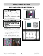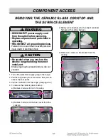
3-5
COMPONENT ACCESS
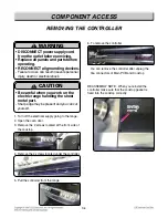
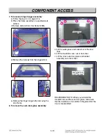
5. To remove the Key PCB assembly remove the 2
screws under the controller.
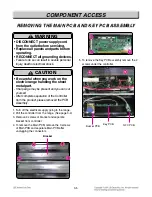
REMOVING THE MAIN PCB AND KEY PCB ASSEMBL
REMOVING THE MAIN PCB AND KEY PCB ASSEMBL
Y
Y
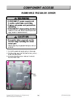
1. Turn off the electrical supply going to the range.
2. Pull the controller from the range. (See page 3-4)
3. Remove 4 screws of bracket and separate
bracket from controller.
4. To remove the Main PCB, remove the 3 screws
of Main PCB and separate Main PCB after
unplugging the connectors.
Buzzer PCB
NFC PCB
Key PCB
WARNING
• DISCONNECT power supply cord
from the outlet before servicing.
• Replace all panels and parts before
operating.
• RECONNECT all grounding devices.
- Failure to do so can result in severe personal
injury, death or electrical shock.
!
CAUTION
• Be careful when you work on the
electric range handling the sheet
metal part.
- Sharp edge may be present and you can cut
yourself.
- After complete separation of the Controller
from the product, please removed the PCB
Assembly.
!
Bracket
Summary of Contents for LSE4613BD
Page 49: ...5 3 OVEN LIGHT CR COOK TOP ELEMENT For Model LSE4613ST LSE4613BD LR RR COOK TOP ELEMENT ...
Page 50: ...5 4 RF COOK TOP ELEMENT LF COOK TOP ELEMENT For Model LSE4613ST LSE4613BD ...
Page 51: ...5 5 WARM PROOF EASY CLEAN BROIL ...
Page 82: ...EXPLODED VIEW EV INTRODUCTION 9504 9501 9506 Customer Model Product Code SVC Model MODEL ...
Page 85: ... EV COOKTOP PARTS 3056 3215 3006 3016 330M 330H 3205 3022 3204 330S 330S 301C ...
Page 88: ......

