3-1
COMPONENT ACCESS
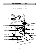
This section instructs you on how to service each component inside the range. The components and their
locations are shown below.
COMPONENT LOCA
COMPONENT LOCA
TIONS
TIONS
Broil Heater
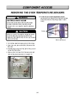
Oven Sensor
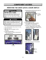
Door Switch
Surface Elements
Door Locking Motor
& Micro Switch
Cook Top
Relay PCB
Main PCB
Cook Top
Display PCB
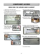
Bake Heater
Hinge Hanger
Warming Drawer
Heater
Warming Drawer
Sensor
Oven Light
LVT
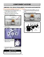
Convection Heater
Door Latch Assembly
Convection Motor
Oven Relay PCB
Thermal Fuse
Summary of Contents for LRE30451
Page 1: ...Service Digital Appliance TRAINING MANUAL ELECTRIC RANGE LRE30451 LRE30755 ...
Page 8: ......
Page 9: ......
Page 11: ...j j j j LRE30451 LRE30755 ...
Page 67: ...8 1 APPENDIX A SCHEMATIC DIAGRAM OF PCB ...
Page 73: ...10 3 WARMNING DRAWER SELF CLEANING For Model LRE30755SW SB ST ...
Page 74: ...10 4 CLOCK DISPLAY ON CR Warming Zone CONV BAKE CONV ROAST For Model LRE30755SW SB ST ...
Page 90: ......
Page 91: ......
Page 92: ......

