3-8
COMPONENT ACCESS
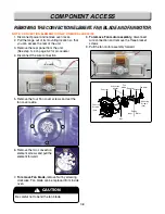
1. Disconnect power and remove oven racks.
2. Pull the range out of its mounting location so that
you can access the rear of the unit.
3. Remove the rear panel from the unit.
(See step 3~4 on page 3-2 for procedure)
4. Disconnect the wire connection.
5. Remove the four Fan cover screws and set the
fan cover aside.
6. Remove the two convection
element screws and pull the
element forward.
7.
To remove Fan blade,
remove Nut by screwing
clockwise. Fan blade can be replaced from inside
oven.
8.
To remove Fan motor assembly
, disconnect
wire connection and remove the three bracket
screws
9. Pull the fan motor assembly forward.
REMOVING THE CONVECTION ELEMENT
REMOVING THE CONVECTION ELEMENT
, F
, F
AN BLADE AND F
AN BLADE AND F
AN MOT
AN MOT
OR
OR
Fan cover
Convection
heater
Nut
Fan cover
Screws
(4ea)
Mounting
Screws
(3ea)
Cavity
Inner Outer
Fan
blade Support
Washer
Fan motor
!
CAUTION
Be careful not to bend the fan blade.
Nut
Nut
Nut
Nut
Nut
Nut
Nut
Nut
Nut
Nut
Nut
Nut
Nut
Nut
Nut
Nut
Nut
Nut
Nut
Nut
Nut
Nut
Nut
Nut
Nut
Nut
Nut
Nut
Nut
Nut
NOTE: CONVECTION ELEMENT IS ONLY ON MODEL LRE30755
Summary of Contents for LRE30451
Page 1: ...Service Digital Appliance TRAINING MANUAL ELECTRIC RANGE LRE30451 LRE30755 ...
Page 8: ......
Page 9: ......
Page 11: ...j j j j LRE30451 LRE30755 ...
Page 67: ...8 1 APPENDIX A SCHEMATIC DIAGRAM OF PCB ...
Page 73: ...10 3 WARMNING DRAWER SELF CLEANING For Model LRE30755SW SB ST ...
Page 74: ...10 4 CLOCK DISPLAY ON CR Warming Zone CONV BAKE CONV ROAST For Model LRE30755SW SB ST ...
Page 90: ......
Page 91: ......
Page 92: ......

