7-3
F-CODE FLOW CHART
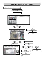
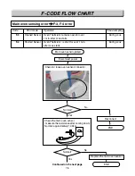
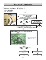
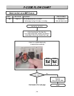
Door lock system error
F-2 error
Normal?
Yes
Yes
Yes
END
No
Replace the micro switch
Normal?
Normal?
END
No
Replace the door locking motor
END
No
Reconnect
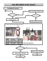
Check the door locking motor (measure the resistance)
normal: approximately 2.6k
Ω
abnormal: infinite or below 5
Ω
Remove the main PCB (009A) harness
and pull the PCB (009A) forward from the PCB case
Check for loose connector (Front) (main PCB CN4)
Front
CN4
CN4
CN4
CN4
CN4
CN4
CN4
CN4
CN4
CN4
CN4
CN4
CN4
CN4
CN4
CN4
CN4
CN4
CN4
CN4
CN4
CN4
CN4
CN4
CN4
CN4
CN4
CN4
CN4
CN4
3
2
1
Summary of Contents for LRE30451
Page 1: ...Service Digital Appliance TRAINING MANUAL ELECTRIC RANGE LRE30451 LRE30755 ...
Page 8: ......
Page 9: ......
Page 11: ...j j j j LRE30451 LRE30755 ...
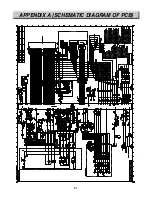
Page 67: ...8 1 APPENDIX A SCHEMATIC DIAGRAM OF PCB ...
Page 73: ...10 3 WARMNING DRAWER SELF CLEANING For Model LRE30755SW SB ST ...
Page 74: ...10 4 CLOCK DISPLAY ON CR Warming Zone CONV BAKE CONV ROAST For Model LRE30755SW SB ST ...
Page 90: ......
Page 91: ......
Page 92: ......


