11. DISASSEMBLY INSTRUCTIONS
-34-
IMPORTANT NOTES:
THE UNIT MUST BE DISCONNECTED FROM
THE ELECTRICAL OUTLET WHEN MAKING
REPAIRS, REPLACEMENTS, ADJUSTMENTS
AND CONTINUITY CHECKS.
WHEN RECONNECTING THE WIRE LEADS TO
ANY PART, MAKE SURE THE WIRING CONNE-
CTIONS AND LEAD COLORS ARE CORRECTLY
MATCHED ACCORDING TO THE OVERALL CIR-
CUIT DIAGRAM. (ESPECIALLY THE SWITCHES
AND THE HIGH VOLTAGE CIRCUIT.)
A. REMOVING POWER AND CONTROL
CIRCUIT BOARD (Figures 1, 2 and, 3)
(1) Remove the a screw securing the control panel
assembly to the oven cavity.
(2) Remove the control panel by pushing it upward.
(3) Remove the connectors (cn1,cn3,cn5) and wire
leads (RY1,RY2) from the circuit board.
(4) Remove 5 screws securing the circuit board.
(Relay 2)-White
Relay 2
Relay 1
(CN1)
Control Bracket
FPC Connector(S1)
Circuit Board
(Relay 5)-Blue
Circuit Board
(Relay )-White
Relay 2
(CN1)
Control Bracket
FPC Connector(S1)
Relay
Circuit Board
Circuit Board
(Relay 2)-White
Relay 2
Relay 1
(CN1)
Control Bracket
FPC Connector(S1)
Circuit Board
(Relay 5)-Blue
Circuit Board
(Relay )-White
Relay 2
(CN1)
Control Bracket
FPC Connector(S1)
Relay
Circuit Board
Circuit Board
(Relay 2)-White
Relay 2
Relay 1
(CN1)
Control Bracket
FPC Connector(S1)
Circuit Board
(Relay 5)-Blue
Circuit Board
(Relay )-White
Relay 2
(CN1)
Control Bracket
FPC Connector(S1)
Relay
Circuit Board
Circuit Board
(5) Remove the FPC connector from the terminal
socket following HOW TO REMOVE THE FPC
CONNECTOR on the next page.
(6) Remove the circuit board from the control
bracket carefully.
Figure 1
Figure 2
Figure 3
Summary of Contents for LMV1762SB
Page 7: ... 7 4 OPERATION 4 1 Control Panel 12 14 15 17 23 20 16 21 22 19 13 2 3 1 6 7 9 11 8 10 4 5 18 ...
Page 10: ... 10 5 2 Key Matrix KEY MATRIX KEY MATRIX ...
Page 14: ... 14 6 4 Troubleshooting No Display or Dead ...
Page 16: ... 16 Keypad Failure ...
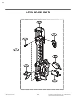
Page 44: ...W102 4000 4002 4003 4001 4004 4002 LATCH BOARD PARTS EV ...
Page 48: ......


