4-26
Service Manual
4080-001
Power Supply Removal
Note: Always unplug the printer from the electrical outlet. High
voltage is present in the power supply as long as it is plugged into
the electrical outlet.
1. Remove the input / output tray assembly.
2. Remove all covers (except the base), refer to
“Covers and
Doors” on page 4-3
.
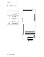
3. Disconnect the power supply cable from the controller board at
(J2).
4. Disconnect the ground strap from the right side of the power
supply.
5. Remove the ground screw from behind the (J2) connector on
the controller card.
6. Depress the clips on both sides of the power supply and slide
the power supply out of the machine.
Note: When replacing the power supply, be sure the metal tab on
the left side of the power supply is inserted under the controller
board.
Tray 2 Sensor Removal
1. Remove the input / output tray assembly.
2. Remove all covers, refer to
“Covers and Doors” on page 4-3
.
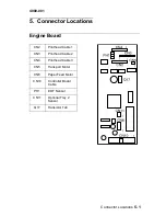
3. Disconnect the tray 2 sensor from the engine board (CN11) and
note the routing of the cable.
4. Depress the clips on the outside of the right side frame and
remove the sensor.
Summary of Contents for Optra Color 45
Page 11: ...xi 4080 001 ...
Page 12: ...xii Service Manual 4080 001 ...
Page 22: ...1 10 Service Manual 4080 001 ...
Page 68: ...3 16 Service Manual 4080 001 ...
Page 71: ...Repair Information 4 3 4080 001 Covers and Doors ...
Page 78: ...4 10 Service Manual 4080 001 Frames ...
Page 82: ...4 14 Service Manual 4080 001 Paper Feed ...
Page 86: ...4 18 Service Manual 4080 001 Electronics ...
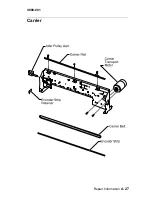
Page 95: ...Repair Information 4 27 4080 001 Carrier ...
Page 99: ...Repair Information 4 31 4080 001 Maintenance Station ...
Page 104: ...6 2 Service Manual 4080 001 ...
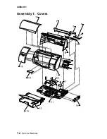
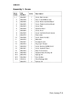
Page 106: ...7 2 Service Manual 4080 001 Assembly 1 Covers ...
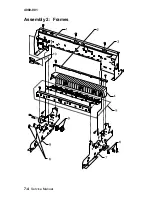
Page 108: ...7 4 Service Manual 4080 001 Assembly 2 Frames ...
Page 110: ...7 6 Service Manual 4080 001 Assembly 3 Paper Feed ...
Page 112: ...7 8 Service Manual 4080 001 Assembly 4 Electronics ...
Page 114: ...7 10 Service Manual 4080 001 Assembly 5 Carrier ...
Page 116: ...7 12 Service Manual 4080 001 Assembly 6 Carrier Transport ...
Page 118: ...7 14 Service Manual 4080 001 Assembly 7 Maintenance Station ...


