background image


11


where you put the switch should be clean, smooth, level and sturdy. Make sure there is 

enough clearance around the switch to allow attachment of cables, power cord and allow 

air circulation. 


Attaching Rubber Pads


A.  Make sure mounting surface on the bottom of the switch is grease and dust free. 

B.  Remove adhesive backing from your Rubber Pads. 

C.  Apply the Rubber Pads to each corner on the bottom of the switch. These footpads 

can prevent the switch from shock/vibration. 


Power On   


Connect the power cord to the power socket on the rear panel of the switch. The other 

side of power cord connects to the power outlet. The internal power supply of the switch 

works  with  voltage  range  of  AC  in  the  100-240VAC/  Frequency  of  50~60Hz,  and  the 

redundant power of DC 48V. Check the power indicator on the front panel to see if power 

is properly supplied. 

Summary of Contents for GSW-0891

Page 1: ...GSW 0891 8 Port PoE Fast Ethernet TP 2 Port Gigabit Combo L2 SNMP Switch User Manual Ver 1 00 0711...

Page 2: ...n a particular installation If this equipment does cause harmful interference to radio or television reception which can be determined by turning the equipment off and on the user is encouraged to try...

Page 3: ...al Dimension 8 Front Panel 8 LED Indicators 9 Rear Panel 10 Desktop Installation 10 Attaching Rubber Pads 11 Power On 11 Network Application 12 Small Workgroup 13 Segment Bridge 14 Console Management...

Page 4: ...40 SNTP Commands Set 41 X ring Commands Set 43 Web Based Management 44 About Web based Management 44 Preparing for Web Management 44 System Login 44 System Information 45 IP Configuration 46 DHCP Conf...

Page 5: ...66 VLAN configuration 68 VLAN configuration Port based VLAN 68 802 1Q VLAN 71 802 1Q Configuration 72 Group Configuration 73 Rapid Spanning Tree 74 RSTP System Configuration 74 RSTP Port Configuration...

Page 6: ...93 Static MAC Address 93 MAC Filtering 94 All MAC Addresses 95 Power over Ethernet 97 Factory Default 98 Save Configuration 99 System Reboot 99 Troubleshooting 100 Incorrect connections 100 Faulty or...

Page 7: ...ause the Power Sourcing Equipment PSE tests whether a networked device is PoE capable power is never transmitted unless a Powered Device is at other end of the cable It also continues to monitor the c...

Page 8: ...1p Class of Service Per port provides 4 priority queues Port Base Tag Base and Type of Service Priority Port Mirror Monitor traffic in switched networks TX Packet only RX Packet only Both of TX and RX...

Page 9: ...adcast Multicast Packet Filter Control System Event Log System Log Server Client SMTP e mail Alert SNMP Trap Device cold start Authentication failure X ring topology changed Port Link up Link down TFT...

Page 10: ...t backup feature and recovery time below 300ms Quality of service The quality of service determined by port Tag and IPv4 Type of service IPv4 IPv6 Different Service Class of Service Supports IEEE 802...

Page 11: ...icast packet Broadcast Multicast packet Broadcast only and all of packet The packet filter rate can be set as 100Kbps 10 100 and 256Mbps 1000 User Authentication Supports IEEE802 1x User Authenticatio...

Page 12: ...de Configuration Upload and Download Supports binary format configuration file for system quick installation TFTP backup and restore Package Contents Unpack the contents of the 8 10 100TX 2 Gigabit co...

Page 13: ...IC Combo with 8 PoE Injectors Managed Four Rubber Pads RS 232 cable Power Cord User Manual Compare the contents of the package with the standard checklist above If any item is missing or damaged pleas...

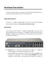
Page 14: ...opper Mini GBIC Combo with 8 PoE Injectors Managed Switch consists of 8 x 10 100Base TX RJ 45 Ethernet ports Auto MDI MDIX 2 Giga port and 2 Mini GBIC ports The LED Indicators are also located on the...

Page 15: ...ble provides descriptions of LED status and their meaning LED Status Description Green Power On Power OFF No power inputs Green The port is supplying power to the connected powered device FWD port 1 8...

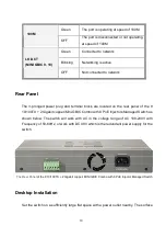
Page 16: ...n the rear panel of the 8 10 100TX 2 Gigabit copper Mini GBIC Combo with 8 PoE Injectors Managed Switch as shown below The switch will work with AC in the voltage range of AC 100 240V with Frequency o...

Page 17: ...from your Rubber Pads C Apply the Rubber Pads to each corner on the bottom of the switch These footpads can prevent the switch from shock vibration Power On Connect the power cord to the power socket...

Page 18: ...fic based on the destination address Using the uplink port Giga Combo port the switch can connect with another switch or hub to interconnect other small switched workgroups to form a larger switched n...

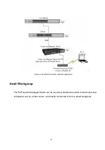
Page 19: ...hernet Switch network application Small Workgroup The PoE Injector Managed Switch can be used as a standalone switch to which personal computers server printer server are directly connected to form a...

Page 20: ...on for department users to connect to the corporate backbone In the illustration below two Ethernet switches with PCs print server and local server attached are both connected to the switch All the de...

Page 21: ...15 Segment Bridge application...

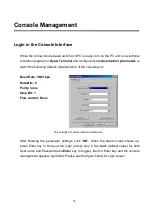
Page 22: ...tics of the console port Baud Rate 9600 bps Data Bits 8 Parity none Stop Bit 1 Flow control None The settings of communication parameters After finishing the parameter settings click OK When the blank...

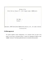
Page 23: ...gement The system supports console management CLI command After you login to the system you will see a command prompt To enter CLI management interface enter enable command The following table lists t...

Page 24: ...witch Enter logout or quit The user commands available at the user level are a subset of those available at the privileged level Use this mode to Perform basic tests Display system information Privile...

Page 25: ...a whole VLAN database Enter the vlan database command while in privileged EXEC mode switch vlan To exit to user EXEC mode enter exit Use this mode to configure VLAN specific parameters Interface conf...

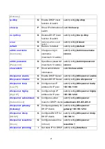
Page 26: ...name System Name G Configure system name switch config system name xxx system location System Location G Set switch system location string switch config system location xxx system description System...

Page 27: ...er switch config dhcpserver enable Dhcpserver disable G Disable DHCP Server switch config no dhcpserver dhcpserver lowip Low IP G Configure low IP address for IP pool switch config dhcpserver lowip 19...

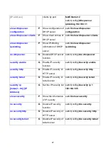
Page 28: ...ver security enable G Enable IP security function switch config security enable security http G Enable IP security of HTTP server switch config security http security telnet G Enable IP security of te...

Page 29: ...mode of operation for Fast Ethernet the speed can t be set to 1000 if the port isn t a giga port switch config interface fastEthernet 2 switch config if speed 100 no flowcontrol I Disable flow control...

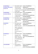
Page 30: ...ingress limit frame type to only accept broadcast frame switch config interface fastEthernet 2 switch config if bandwidth type broadcast only bandwidth in Value I Set interface input bandwidth Rate Ra...

Page 31: ...fig interface fastEthernet 2 switch config if show interface status show interface accounting I show interface statistic counter switch config interface fastEthernet 2 switch config if show interface...

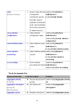
Page 32: ...upID Port list nolacp G Assign a static trunk group GroupID 1 4 Port list Member port list This parameter could be a port range ex 1 4 or a port list separate by a comma ex 2 3 6 switch config aggrega...

Page 33: ...based VALN switch vlan vlan port based grpname test grpid 2 port 2 4 or switch vlan vlan port based grpname test grpid 2 port 2 3 4 show vlan GroupID or show vlan V Show VLAN information switch vlan s...

Page 34: ...3 hybrid link untag 5 tag 6 8 vlan 8021q trunk PortNumber access link untag UntaggedVID V Assign a access link for VLAN by trunk group switch vlan vlan 8021q trunk 3 access link untag 33 vlan 8021q tr...

Page 35: ...change the interval between messages the spanning tree receives from the root switch If a switch does not receive a bridge protocol data unit BPDU message from the root switch within this interval it...

Page 36: ...spanning tree cost interface configuration command to set the path cost for Spanning Tree Protocol STP calculations In the event of a loop spanning tree considers the path cost when selecting an inte...

Page 37: ...switch config interface fastEthernet 2 switch config if stp admin non s tp False show spanning tree E Displays a summary of the spanning tree states switch show spanning tree no spanning tree G Disab...

Page 38: ...oping function switch config igmp enable Igmp query auto G Set IGMP query to auto mode switch config Igmp query auto Igmp query force G Set IGMP query to force mode switch config Igmp query force show...

Page 39: ...move an entry of MAC address table of interface static switch config interface fastEthernet 2 switch config if no mac address table static hwaddr 000012345678 no mac address table filter hwaddr MAC G...

Page 40: ...emove Switch config no snmp server host 192 168 1 50 snmpv3 context name Context Name G Configure the context name switch config snmpv3 context name Test snmpv3 user User Name group Group Name passwor...

Page 41: ...ied community switch config no snmp community strings public no snmp server host Host address G Remove the SNMP server host switch config no snmp server 192 168 1 50 no snmpv3 user User Name G Remove...

Page 42: ...nitor rx monitor tx G Set TX destination port of monitor function switch config monitor tx show monitor P Show port monitor information switch show monitor monitor RX TX Both I Configure source port o...

Page 43: ...guration command to change the radius server port switch config 8021x system serverport 1815 8021x system accountport port ID G Use the 802 1x system account port global configuration command to chang...

Page 44: ...nd to set the supplicant timeout switch config 8021x misc supportimeout 20 8021x misc servertimeout sec G Use the 802 1x misc server timeout global configuration command to set the server timeout swit...

Page 45: ...etstar Commands Level Description Defaults Example backup flash backup_cfg G Save configuration to TFTP and need to specify the IP of TFTP server and the file name of image switch config backup flash...

Page 46: ...P server IP switch config smtp serverip 192 168 1 5 smtp authentication G Enable SMTP authentication switch config smtp authentication smtp account account G Configure authentication account switch co...

Page 47: ...switch config no event device cold start no event authentication failure G Disable Authentication failure event typ switch config no event authentication failure no event X ring topology change G Dis...

Page 48: ...e G Set offset of daylight saving time if SNTP function is inactive this command can t be applied switch config sntp daylight offset 3 sntp ip IP G Set SNTP server IP if SNTP function is inactive this...

Page 49: ...2nd Ring Port switch config Xring ringport 7 8 Xring couplingport Coupling Port G Configure Coupling Port switch config Xring couplingport 1 Xring controlport Control Port G Configure Control Port swi...

Page 50: ...Internet Explorer 6 0 And it is applied with Java Applets for reducing network bandwidth consumption enhance access speed and present an easy viewing screen Preparing for Web Management Before using...

Page 51: ...er Main interface System Information Assign the system name and location and view the system information System Name Assign the system name of the switch The maximum length is 64 bytes System Location...

Page 52: ...he default value is 192 168 16 254 DNS1 The abbreviation of Domain Name Server an Internet service that translates domain name into IP addresses Domain name are alphabetic which are easy to be remembe...

Page 53: ...cause the software keeps track of IP addresses rather than requiring an administrator to manage the task This means that a new computer can be added to a network without the hassle of manually assigni...

Page 54: ...ay The gateway in your network DNS The IP Address of the Domain Name Server in your network Lease Time sec It is the time period that system will reset the dynamic IP assignment to ensure the dynamic...

Page 55: ...Assign the dynamic IP address to the port When the device is connecting to the port and asks for IP assigning the system will assign the IP address that has been assigned before to the connected devic...

Page 56: ...P Firmware File Name The name of firmware image And then click Apply Update Firmware interface TFTP Restore Configuration Restore EEPROM value from TFTP server TFTP Server IP Address Key in the TFTP s...

Page 57: ...ackup Configuration interface System Event Log Configuration Configure the system event mode which you want to collect and system log server IP System Log Client Mode Select the system log mode client...

Page 58: ...e or disable the email alert function SMTP Server IP set up the mail server IP address when Email Alert enabled this function will then be available Sender key in a complete email address e g switch10...

Page 59: ...xisting email account on the mail server which you had set up in SMTP Server IP Address column Password The email account password Confirm Password reconfirm the password Rcpt e mail Address 1 6 you c...

Page 60: ...opology change Mark the checkbox to select the event When selected events occur the system will produce the logs Device cold start When the device executes cold start action the system will produce a...

Page 61: ...Link UP Link Down and Link UP Link Down Disable means no event is selected Link UP The system will result a log message when port connection is up only Link Down The system will result a log message...

Page 62: ...ht saving time period 3 UTC Timezone set the switch location time zone The following table lists the different location time zone for your reference Local Time Zone Conversion from UTC Time at 12 00 U...

Page 63: ...ish Winter 1 hour 1 pm EET Eastern European USSR Zone 1 2 hours 2 pm BT Baghdad USSR Zone 2 3 hours 3 pm ZP4 USSR Zone 3 4 hours 4 pm ZP5 USSR Zone 4 5 hours 5 pm ZP6 USSR Zone 5 6 hours 6 pm WAST Wes...

Page 64: ...riod set up the Daylight Saving beginning time and Daylight Saving ending time Both will be different in every year 6 Daylight Saving Offset mins set up the offset time 7 Switch Timer Displays the swi...

Page 65: ...P1 IP10 will be allowed to access via HTTP service Enable Telnet Server when checked the IP addresses among Security IP1 IP10 will be allowed to access via telnet service Security IP 1 10 Assign up to...

Page 66: ...Up or Down State It s set by Port Control When the state is disabled the port will not transmit or receive any packet Tx Good Packet The counts of transmitting good packets via this port Tx Bad Packe...

Page 67: ...Current port status The port can be set to disable or enable mode If the port setting is disable then will not receive or transmit any packet 3 Negotiation set auto negotiation status of port 4 Speed...

Page 68: ...nk to that Link Aggregation Group and enable its transmission and reception functions in an orderly manner Link aggregation lets you group up to 4 ports into one dedicated connection This feature can...

Page 69: ...four ports to be aggregated at the same time With LACP static trunk group the exceed ports are standby and can be aggregated later if work ports fail If it is local static trunk group the number of p...

Page 70: ...tor Setting interface Port Trunk Aggregator Information When you have setup the aggregator setting with LACP disabled you will see the local static trunk group information here Port Trunk Aggregator I...

Page 71: ...omatically send LACP protocol packets and responds only if it receives LACP protocol packets from the opposite device Note 1 A link has either two active LACP ports or one active port can perform dyna...

Page 72: ...use one of two ports for monitoring RX traffic only and the other one for TX traffic only User can connect mirror port to LAN analyzer or Netxray Source Port The ports that user wants to monitor All...

Page 73: ...pe Rate Limiting interface All the ports support port ingress and egress rate control For example assume port 1 is 10Mbps users can set it s effective egress rate as 1Mbps ingress rate as 500Kbps The...

Page 74: ...y The switch supports port based and 802 1Q tagged based VLAN The default configuration of VLAN operation mode is Disable VLAN Configuration interface VLAN configuration Port based VLAN Packets can go...

Page 75: ...ormation about the packet such as the protocol VLAN Port Based interface Click Add to add a new VLAN group The maximum VLAN group is up to 256 VLAN groups Entering the VLAN name group ID and grouping...

Page 76: ...u will see the VLAN displays Use Delete button to delete unwanted VLAN Use Edit button to modify existing VLAN group Note Remember to execute the Save Configuration action otherwise the new configurat...

Page 77: ...ers You can create Tag based VLAN and enable or disable GVRP protocol There are 256 VLAN groups to provide configuring Enable 802 1Q VLAN the all ports on the switch belong to default VLAN VID is 1 Th...

Page 78: ...ink Type Access Link Single switch only allows user to group ports by setting the same VID to those ports Trunk Link The extended application of Access Link While the ports are set in this type they c...

Page 79: ...Tagged VID Assign the tagged frame VID 6 Click Apply Group Configuration Edit the existing VLAN Group 1 Select the VLAN group in the table list 2 Click Apply Group Configuration interface 3 You can Ch...

Page 80: ...TP protocol RSTP System Configuration User can view spanning tree information about the Root Bridge User can modify RSTP state After modification click Apply button RSTP mode User must enable or disab...

Page 81: ...et to check RSTP current status Enter a value between 1 through 10 Forward Delay Time 4 30 The number of seconds a port waits before changing from its Rapid Spanning Tree Protocol learning and listeni...

Page 82: ...hether the port concerned can only be connected to exactly one other bridge i e it is served by a point to point LAN segment or can be connected to two or more bridges i e it is served by a shared med...

Page 83: ...c on an IP network SNMP enables network administrators to manage network performance find and solve network problems and plan for network growth Network management systems learn of problems by receivi...

Page 84: ...to display MIB object information and to set MIB objects 1 Click Add 2 To remove the community string select the community string that you have defined and click Remove You cannot edit the name of th...

Page 85: ...define management stations as trap manager enter SNMP community strings and selects the SNMP version 1 IP Address Enter the IP address of trap manager 2 Community Enter the community string 3 Trap Ver...

Page 86: ...ick Add to add context name Click Remove to remove unwanted context name User Profile Configure SNMP v3 user table User ID Set up the user name Authentication Password Set up the authentication passwo...

Page 87: ...81 SNMP V3 configuration interface...

Page 88: ...ntext Prefix Set up the context name Group Name Set up the group Security Level Set up the access level Context Match Rule Select the context match rule Read View Name Set up the read view Write View...

Page 89: ...ueue will be processed at the same time in accordance with the 8 4 2 1 policy rule Use the strict priority scheme Always higher queue will be process first except higher queue is empty Priority Type T...

Page 90: ...84 rule Click Apply QoS Configuration interface...

Page 91: ...iddle low and lowest The default value is Lowest priority for each level When the IP packet is received the system will check the TOS level value in the IP packet that has received For example user se...

Page 92: ...e host wants to be or is a member of a given group indicated in the report message Leave Group A message sent by a host to the querier to indicate that the host has quit being a member of a specific m...

Page 93: ...87 IGMP Configuration interface...

Page 94: ...p If there are 2 or more switches in master mode then software will select the switch with lowest MAC address number as the ring master The X Ring master ring mode will be enabled by the X Ring config...

Page 95: ...assign the control port to form a couple ring group between the two X rings Enable Dual Homing Set up one of the ports on the switch to be the Dual Homing port For a switch there is only one Dual Homi...

Page 96: ...n configure the parameters of this function 1 IEEE 802 1x Protocol Enable or disable 802 1x protocol 2 Radius Server IP Set the Radius Server IP address 3 Server Port Set the UDP destination port for...

Page 97: ...ject The specified port is required to be held in the unauthorized state Accept The specified port is required to be held in the Authorized state Authorized The specified port is set to the Authorized...

Page 98: ...sion 3 Supplicant Timeout Set the period of time the switch waits for a supplicant response to an EAP request 4 Server Timeout Set the period of time the switch waits for a server response to an authe...

Page 99: ...the switch This saves the switch from having to re learn a device s MAC address when the disconnected or powered off device is active on the network again You can add modify delete a static MAC addres...

Page 100: ...rom filtering table select the MAC address and click Delete Static MAC Addresses interface MAC Filtering By filtering MAC address the switch can easily filter pre configured MAC address and reduce the...

Page 101: ...e select the MAC address and click Delete All MAC Addresses You can view the port information of the connected device s MAC address and related devices MAC address 1 Select the port 2 The selected por...

Page 102: ...96 All MAC Address interface...

Page 103: ...column shows the power source which is supplying Power Source 1 AC This column shows the supplying power value of power source 1 Power Source 2 AC DC This column shows the supplying power of power sou...

Page 104: ...t method Classification When this check box is marked the system will limit the power supply to the powered device in accordance with the related class Legacy Check it to support the legacy power devi...

Page 105: ...at you have made in the system To ensure the all configuration will be saved Click Save to save the all configuration to the flash memory Save Configuration interface System Reboot Reboot the switch i...

Page 106: ...Faulty or loose cables Look for loose or obviously faulty connections If they appear to be OK make sure the connections are snug If that does not correct the problem try a different cable Non standard...

Page 107: ...that will severely impact your network performance Diagnosing LED Indicators The switch can be easily monitored through panel indicators which describes common problems user may encounter and where u...

Page 108: ...Rapid spanning tree IEEE802 1p Class of service IEEE802 1Q VLAN Tag IEEE 802 1x user authentication Radius LED Indicators System Power Green 10 100TX Port Link Activity Green 100Mbps Green Gigabit co...

Page 109: ...tem throughput up to 8 3Mpps Back plane 5 6Gbps MAC address 8K MAC address table with Auto learning function Flash ROM 4Mbytes DRAM 32Mbytes Packet Buffer 1Mbits for packet buffer Power Supply 100 240...

Page 110: ...104 Dimensions 270mm W x 210mm D x 44mm H...

Reviews: