background image

Statement 3

CAUTION:
When laser products (such as CD-ROMs, DVD drives, fiber optic devices, or transmitters) are
installed, note the following:

• Do not remove the covers. Removing the covers of the laser product could result in exposure to

hazardous laser radiation. There are no serviceable parts inside the device.

• Use of controls or adjustments or performance of procedures other than those specified herein

might result in hazardous radiation exposure.

DANGER

Some laser products contain an embedded Class 3A or Class 3B laser diode. Note the following:

Laser radiation when open. Do not stare into the beam, do not view directly with optical
instruments, and avoid direct exposure to the beam.

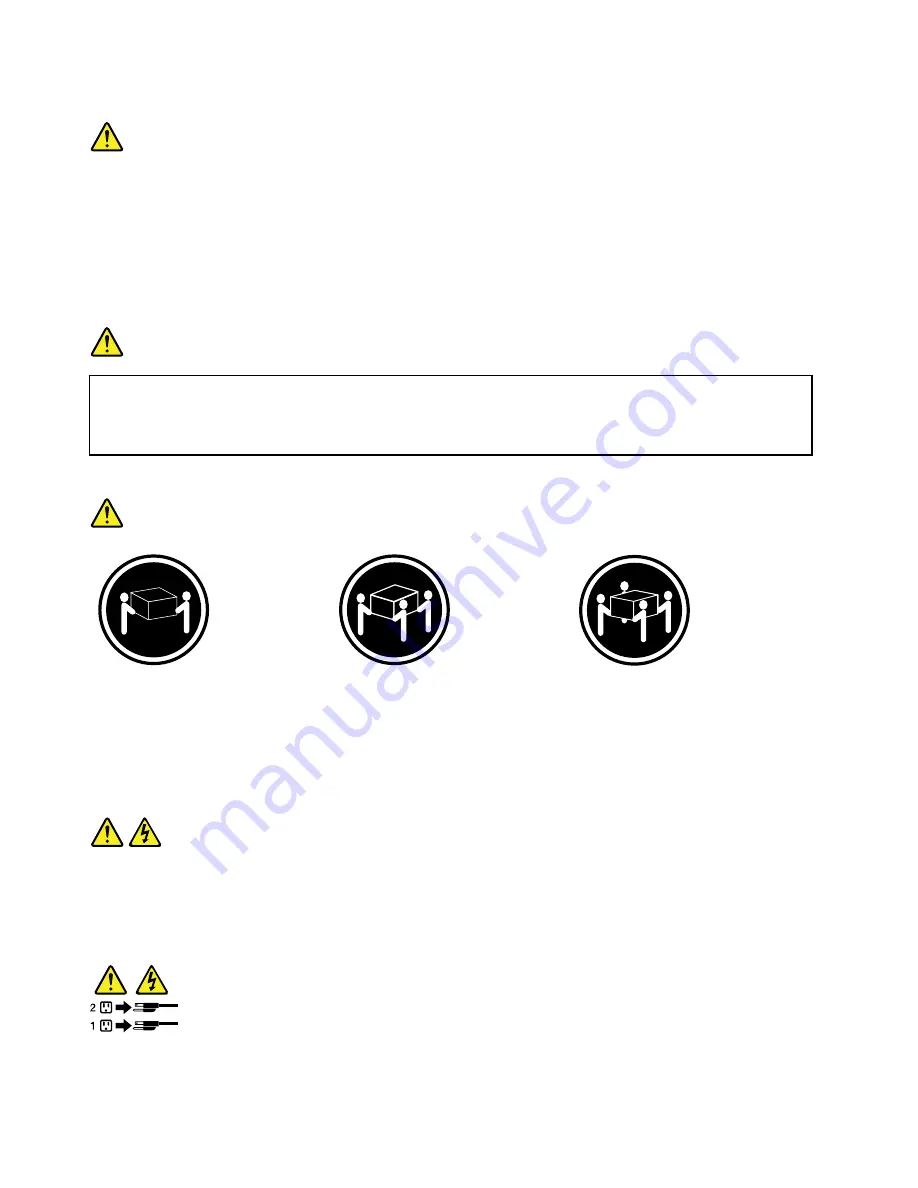
Statement 4

≥ 18 kg (39.7 lb)

≥ 32 kg (70.5 lb)

≥ 55 kg (121.2 lb)

< 32 kg (70.5 lb)

< 55 kg (121.2 lb)

< 100 kg (220.5 lb)

CAUTION:
Use safe practices when lifting.

Statement 5

CAUTION:
The power control button on the device and the power switch on the power supply do not turn off
the electrical current supplied to the device. The device also might have more than one power
cord. To remove all electrical current from the device, ensure that all power cords are disconnected
from the power source.

vi

ThinkServer TS130 Hardware Maintenance Manual

Summary of Contents for ThinkServer TS130 1098

Page 1: ...ThinkServer TS130 Hardware Maintenance Manual Machine Types 1098 1100 1105 and 1106 ...

Page 2: ...ur product Safety information on page iii Appendix A Notices on page 99 Eighth Edition March 2015 Copyright Lenovo 2011 2015 LIMITED AND RESTRICTED RIGHTS NOTICE If data or software is delivered pursuant a General Services Administration GSA contract use reproduction or disclosure is subject to restrictions set forth in Contract No GS 35F 05925 ...

Page 3: ...ive 39 Installing removing or replacing hardware devices 42 Replacing the power supply assembly 42 Replacing the heat sink and fan assembly 45 Replacing the front audio and USB assembly 47 Replacing the front fan assembly 48 Replacing the rear fan assembly 50 Replacing the microprocessor 52 Replacing the system board battery 55 Replacing the system board 56 Completing the parts replacement 58 Conn...

Page 4: ...ou call 96 Calling for service 96 Using other services 97 Purchasing additional services 97 Appendix A Notices 99 Trademarks 100 Important notes 100 Particulate contamination 100 Polyvinyl Chloride PVC cable and cord notice 101 Recycling information 101 Battery return program 102 Requirements for Batteries Containing Perchlorate 103 Important WEEE information 103 Restriction of Hazardous Substance...

Page 5: ...n käyttöä Avant d utiliser le produit veillez à bien lire et comprendre les instructions de sécurité multilingues figurant sur le DVD de documentation fourni avec le produit Πριν χρησιμοποιήσετε το προϊόν βεβαιωθείτε ότι έχετε διαβάσει και κατανοήσει τις οδηγίες ασφάλειας οι οποίες είναι διαθέσιμες σε διάφορες γλώσσες στο DVD τεκμηρίωσης που συνοδεύει το προϊόν Vor Verwendung des Produkts sollten ...

Page 6: ...tacijo ki ste ga prejeli skupaj z izdelkom Antes de utilizar el producto asegúrese de leer y comprender las instrucciones de seguridad multilingües del DVD de documentación que se proporciona con el producto Var noga med att läsa säkerhetsinstruktionerna på dokumentations DVD skivan som följer med produkten innan du börjar använda produkten 使用本產品之前 請務必閱讀並瞭解產品隨附的文件 DVD 上的多國語言版本安全資訊 Bu ürünü kullanm...

Page 7: ... instructed otherwise in the installation and configuration procedures Connect and disconnect cables as described in the following table when installing moving or opening covers on this product or attached devices To connect To disconnect 1 Turn everything OFF 2 First attach all cables to devices 3 Attach signal cables to connectors 4 Attach power cords to outlets 5 Turn devices ON 1 Turn everythi...

Page 8: ...A or Class 3B laser diode Note the following Laser radiation when open Do not stare into the beam do not view directly with optical instruments and avoid direct exposure to the beam Statement 4 18 kg 39 7 lb 32 kg 70 5 lb 55 kg 121 2 lb 32 kg 70 5 lb 55 kg 121 2 lb 100 kg 220 5 lb CAUTION Use safe practices when lifting Statement 5 CAUTION The power control button on the device and the power switc...

Page 9: ...s will not support the weight of the device Statement 8 CAUTION Never remove the cover on a power supply or any part that has the following label attached Hazardous voltage current and energy levels are present inside any component that has this label attached There are no serviceable parts inside these components If you suspect a problem with one of these parts contact a service technician Statem...

Page 10: ...s extended on the rails Statement 14 CAUTION Some accessory or option board outputs exceed Class 2 or limited power source limits You must install the appropriate interconnecting cabling in accordance with your local electrical code requirements Statement 15 CAUTION The power control button on the device may put the device in standby mode instead of turning off the device In addition the device mi...

Page 11: ... V direct current The branch circuit overcurrent protection must be rated in accordance with local electrical code requirements Use 1 3 mm2 or 16 American Wire Gauge AWG copper conductor only not exceeding 3 meters in length Torque the wiring terminal screws to 1 4 newton meters or 12 inch pounds Provide a readily available approved and rated disconnect device in the field wiring Statement 17 CAUT...

Page 12: ...re To determine whether there are any potentially unsafe conditions use the following checklist at the beginning of every service task Begin the checks with the power off and the power cords disconnected Checklist 1 Check exterior covers for damage loose broken or sharp edges 2 Power off the server Disconnect the power cords 3 Check the power cord for a A third wire ground connector in good condit...

Page 13: ...afety information on page iii For information about major component locations and CRU identification see Server components on page 19 For information about installing removing or replacing major FRUs see Chapter 5 Installing removing or replacing hardware on page 23 For a complete listing of FRU information such as FRU part numbers and supported server models go to http www lenovo com serviceparts...

Page 14: ...or if you are using a Linux operating system open the launch htm file located in the root directory of the DVD Note Lenovo maintains pages on the World Wide Web where you can get the latest technical information and download documentation or device drivers and updates Some information in the documents on the documentation DVD might change without notice after the first release of the DVD You can a...

Page 15: ...is document provides information about component locations replacement procedures for major Field Replaceable Units FRUs and troubleshooting and diagnostics This document is updated frequently and the most up to date version is always available in English on the Lenovo Web site at http www lenovo com ThinkServerUserGuides Chapter 1 General information 3 ...

Page 16: ...4 ThinkServer TS130 Hardware Maintenance Manual ...

Page 17: ...ing hardware on page 23 Connect the Ethernet cable and power cord Rear view on page 14 Turn on the server to verify operation Turning on the server on page 60 Review the BIOS settings and customize as needed Starting the Setup Utility program on page 63 Configure Redundant Array of Independent Disks RAID Configuring RAID on page 79 Check for firmware updates Updating the firmware on page 81 Instal...

Page 18: ...6 ThinkServer TS130 Hardware Maintenance Manual ...

Page 19: ...e 1 Server 2 Power cord 3 Material box including printed documentation a documentation DVD and software media Features and specifications The following table provides information about the features and specifications of the server Depending on the server model some features might not be available or some specifications might not apply For information about your specific model use the Setup Utility...

Page 20: ...es with your ThinkServer server Expansion Two optical drive bays System management features Ability to store power on self test POST hardware test results Automatic power on startup Intel Active Management Technology AMT Intel Hyper Threading technology some models Intel Rapid Storage Technology RST Preboot Execution Environment PXE System Management SM UEFI and SM software Wake on LAN Wake on Rin...

Page 21: ...to 80 non condensing 10 per hour Non operating 10 to 90 non condensing 10 per hour Altitude 0 to 2000 m 0 to 6562 ft Security features Computrace Enabling or disabling a device Enabling or disabling USB connectors individually Hard disk drive password Power On Password POP and Administrator Password for UEFI access Startup sequence control Startup without keyboard or mouse Support for an integrate...

Page 22: ... is on the DVD and can be accessed directly from the program interface For detailed information see Using the ThinkServer EasyStartup program on page 82 ThinkServer EasyUpdate Firmware Updater The ThinkServer EasyUpdate Firmware Updater program hereinafter referred to as the Firmware Updater program enables you to maintain your server firmware up to date and helps you avoid unnecessary server outa...

Page 23: ... ThinkServer System Profile Collection Tool For more information see Using a diagnostic program on page 87 Chapter 3 Product overview 11 ...

Page 24: ...12 ThinkServer TS130 Hardware Maintenance Manual ...

Page 25: ...n you contact Lenovo for help the machine type model and serial number information helps support technicians to identify your server and provide faster service The following is a sample of the machine type model and serial number label Machine Type XXXX Model Number XXX S N XXXXXXX Figure 2 Machine type model and serial number label Front view Figure 3 Front control and connector locations on page...

Page 26: ...D 5 USB connectors 2 3 Power on LED Rear view Figure 4 Rear connector locations on page 15 shows the locations of the connectors on the rear of your server Some connectors on the rear of your server are color coded to help you determine where to connect the cables in your server 14 ThinkServer TS130 Hardware Maintenance Manual ...

Page 27: ...external devices such as powered stereo speakers speakers with built in amplifiers headphones multimedia keyboards or the audio line in connector on a stereo system or other external recording device DisplayPort connector Used to attach a high performance monitor a direct drive monitor or other devices that use a DisplayPort connector Microphone connector Used to attach a microphone to your server...

Page 28: ...e a Category 5 Ethernet cable Figure 5 Ethernet status LEDs Ethernet status LED Color Status Description Amber On The connection speed is 1000 Mbps Green On The connection speed is 100 Mbps 1 Left data speed None Off The connection speed is 10 Mbps Yellow On The server is connected to a LAN None Off The server is disconnected from a LAN 2 Right link and activity Yellow Blinking The LAN is connecte...

Page 29: ... Complementary Metal Oxide Semiconductor Recovery jumper 5 Memory slot 3 DIMM3 18 Internal speaker connector 6 Memory slot 4 DIMM4 19 Front audio connector for connecting the microphone and headphone connectors on the front bezel 7 Thermal sensor connector 20 PCI card slots 2 8 24 pin power connector 21 PCI Express x1 card slot 9 Battery 22 PCI Express x16 card slot 10 SATA connectors 1 and 2 SATA...

Page 30: ...y module 5 Rear fan assembly 3 Optical drive 6 Power supply assembly Internal drives Internal drives are devices that your server uses to read and store data You can add drives to your server to increase storage capacity and enable your server to read other types of media Internal drives are installed in bays In this manual the bays are referred to as bay 1 bay 2 and so on Figure 8 Drive bay locat...

Page 31: ...rver components This topic provides information about major component locations and CRU identification For more information about major components see the related topics in Chapter 4 Locating parts controls and connectors on page 13 To remove the server cover and gain access to the inside of the server see Removing the server cover on page 25 For the system board components see Locating parts on t...

Page 32: ...so can install optional service CRUs which might require some technical skills or tools or request that a technician install the optional service CRU under the terms of the applicable warranty service type for your country or region Non CRUs must be replaced only by trained service technicians The following table lists the major FRUs in your server and the CRU identification information For a comp...

Page 33: ...rive Yes No Heat sink and fan assembly No Yes Keyboard Yes No Memory module Yes No Mouse Yes No Optical drive Yes No PCI card available in some models Yes No Power supply assembly No Yes Rear fan assembly No Yes System board battery Yes No System board No No Chapter 4 Locating parts controls and connectors 21 ...

Page 34: ...22 ThinkServer TS130 Hardware Maintenance Manual ...

Page 35: ...ximum levels of performance To download firmware updates for your server go to http www lenovo com drivers and then follow the instructions on the Web page See Updating the firmware on page 81 for more information Before you install optional hardware devices ensure that the server is working correctly If the server is not working correctly see Chapter 7 Troubleshooting and diagnostics on page 87 t...

Page 36: ...utions to avoid static electricity damage Limit your movement Movement can cause static electricity to build up around you Always carefully handle the parts and other components such as PCI Express cards memory modules system boards and microprocessors by edges or frame Do not touch solder joints pins or exposed circuitry Do not leave the device where others can handle and possibly damage the devi...

Page 37: ...ir ducts or air baffles do not remove them while the server is running Operating the server without the air ducts or air baffles might cause the microprocessors to overheat For servers that support up to two microprocessors ensure that the second microprocessor socket always contains a microprocessor or is protected by a microprocessor socket cover Working inside the server with the power on Atten...

Page 38: ... cover such as a padlock or an integrated cable lock See Integrated cable lock on page 61 and Padlock on page 61 5 Remove the two thumbscrews that secure the server cover 6 Press the cover release button on the side of the server and slide the cover to the rear of the server to remove the cover Figure 10 Removing the server cover Removing and reinstalling the front bezel Attention Do not open your...

Page 39: ...tlets and disconnect all cables that are connected to the server 2 Remove the server cover See Removing the server cover on page 25 3 Remove the front bezel by releasing the three plastic tabs on the left side and pivoting the front bezel outward Figure 11 Removing the front bezel Chapter 5 Installing removing or replacing hardware 27 ...

Page 40: ...intain your server by replacing the failing optional hardware devices If you are replacing an optional hardware device perform the removal procedure and then perform the installation procedure for the optional hardware device that you want to replace Installing or replacing a PCI card Attention Do not open your server or attempt any repair before reading and understanding Safety information on pag...

Page 41: ...cover See Removing the server cover on page 25 3 At the rear of the server press the release button 1 to open the PCI card latch 2 Figure 13 Opening the PCI card latch Chapter 5 Installing removing or replacing hardware 29 ...

Page 42: ...e PCI card is held in place by a retaining latch press the card retaining latch 1 as shown to disengage the latch Grasp the PCI card and gently pull it out of the card slot Figure 14 Removing a PCI card 5 Remove the new PCI card from its static protective package 6 Install the new PCI card into the appropriate slot on the system board See Locating parts on the system board on page 17 Note If you a...

Page 43: ... do the following 1 Remove all media from the drives and turn off all attached devices and the server Then disconnect all power cords from electrical outlets and disconnect all cables that are connected to the server 2 Remove the server cover See Removing the server cover on page 25 3 Lay the server on its side for easier operation 4 The Ethernet card is a kind of PCI card See Installing or replac...

Page 44: ...r slots for installing or replacing DDR3 UDIMMs that provide up to a maximum of 32 GB system memory When installing or replacing a memory module use the following guidelines Use 2 GB 4 GB or 8 GB DDR3 UDIMMs in any combination up to a maximum of 32 GB Install memory modules in the sequence of DIMM 2 DIMM 4 DIMM 1 and DIMM 3 See Locating parts on the system board on page 17 If you are installing tw...

Page 45: ...ew memory module open the retaining clips of the memory slot into which you want to install the memory module Figure 17 Opening the retaining clips 7 Touch the static protective package that contains the new memory module to any unpainted metal surface on the outside of the server Then remove the new memory module from the package Chapter 5 Installing removing or replacing hardware 33 ...

Page 46: ...e optical drive Attention Do not open your server or attempt any repair before reading and understanding Safety information on page iii and Guidelines on page 23 This section provides instructions on how to install or replace the optical drive To install or replace an optical drive do the following 1 Remove all media from the drives and turn off all attached devices and the server Then disconnect ...

Page 47: ... then slide the optical drive out of the front of the server Figure 19 Removing the optical drive 5 Slide the new optical drive with the optical drive retainer 1 installed into the drive bay from the front of the server until the optical drive snaps into position Figure 20 Installing the optical drive Chapter 5 Installing removing or replacing hardware 35 ...

Page 48: ...y hard disk drive Attention Do not open your server or attempt any repair before reading and understanding Safety information on page iii and Guidelines on page 23 This section provides instructions on how to replace the primary hard disk drive To replace the primary hard disk drive do the following 1 Remove all media from the drives and turn off all attached devices and the server Then disconnect...

Page 49: ...rom the bracket 7 To install a new hard disk drive into the blue bracket flex the sides of the bracket and align pin 1 pin 2 pin 3 and pin 4 on the bracket with the corresponding holes in the hard disk drive Do not touch the circuit board 5 on the bottom of the hard disk drive Note If you are installing a 2 5 inch hard disk drive install the hard disk drive into a 2 5 inch to 3 5 inch hard disk dr...

Page 50: ...e chassis Press down on the metal latch 2 and pivot the hard disk drive cage into place Then slide the drive cage to the front of the server until it snaps into position Note There are two arrows one on the upper drive cage and one on the hard disk drive cage The arrows are aligned when the hard disk drive is in the correct position Figure 24 Installing the primary hard disk drive 38 ThinkServer T...

Page 51: ...r server or attempt any repair before reading and understanding Safety information on page iii and Guidelines on page 23 To install or replace the secondary hard disk drive do the following 1 Remove all media from the drives and turn off all attached devices and the server Then disconnect all power cords from electrical outlets and disconnect all cables that are connected to the server 2 Remove th...

Page 52: ...ket 8 To install the secondary hard disk drive flex the sides of the bracket properly and align pin 1 pin 2 pin 3 and pin 4 on the bracket with the corresponding holes in the hard disk drive Do not touch the circuit board 5 on the bottom of the hard disk drive Note If you are installing a 2 5 inch hard disk drive install the hard disk drive into a 2 5 inch to 3 5 inch hard disk drive tray first an...

Page 53: ... disk drive cage until it snaps into position 10 Slide the hard disk drive cage with the new hard disk drive into the chassis until it is directly underneath the metal tab 1 Figure 28 Installing the secondary hard disk drive Chapter 5 Installing removing or replacing hardware 41 ...

Page 54: ...Figure 30 Connecting a SATA hard disk drive Installing removing or replacing hardware devices This section provides instructions on how to install remove or replace hardware devices for your server You can maintain your server by replacing the failing hardware devices If you are replacing a hardware device perform the removal procedure and then perform the installation procedure for the hardware d...

Page 55: ...y component that has this label attached There are no serviceable parts inside these components If you suspect a problem with one of these parts contact a service technician To replace the power supply assembly do the following 1 Remove all media from the drives and turn off all attached devices and the server Then disconnect all power cords from electrical outlets and disconnect all cables that a...

Page 56: ...supply assembly is the correct replacement 7 Install the new power supply assembly into the chassis so that the screw holes in the power supply assembly align with those in the chassis 8 Install and tighten the four screws to secure the power supply assembly Note Use only screws provided by Lenovo 9 Reconnect the power supply assembly cables to the system board and each of the drives 10 Secure the...

Page 57: ...e removing the server cover To replace the heat sink and fan assembly do the following 1 Remove all media from the drives and turn off all attached devices and the server Then disconnect all power cords from electrical outlets and disconnect all cables that are connected to the server 2 Remove the server cover See Removing the server cover on page 25 3 Lay the server on its side for easier access ...

Page 58: ...nk and fan assembly on the system board so that the four screws on the heat sink and fan assembly are aligned with the corresponding holes on the system board Make sure that you properly place the heat sink and fan assembly so that you can easily connect the heat sink and fan assembly cable to the microprocessor fan connector on the system board 9 Follow this sequence to install the four screws to...

Page 59: ...ct the front audio and USB assembly cable from the system board See Chapter 4 Locating parts controls and connectors on page 13 5 Note the front audio and USB assembly cable routing and remove the screw that secures the front audio and USB assembly Then remove the front audio and USB assembly from the chassis Figure 34 Removing the front audio and USB assembly 6 Route the new front audio and USB a...

Page 60: ...ll media from the drives and turn off all attached devices and the server Then disconnect all power cords from electrical outlets and disconnect all cables that are connected to the server 2 Remove the server cover See Removing the server cover on page 25 3 Remove the front bezel See Removing and reinstalling the front bezel on page 26 4 Disconnect the front fan assembly cable from the power fan c...

Page 61: ...1 that attach the front fan assembly to the chassis as shown and then completely remove the front fan assembly from the chassis Figure 35 Removing the front fan assembly Chapter 5 Installing removing or replacing hardware 49 ...

Page 62: ...e parts replacement on page 58 Replacing the rear fan assembly Attention Do not open your server or attempt any repair before reading and understanding Safety information on page iii and Guidelines on page 23 This section provides instructions on how to replace the rear fan assembly To replace the rear fan assembly do the following 1 Remove all media from the drives and turn off all attached devic...

Page 63: ... fan assembly by cutting the rubber mounts and gently pulling the rear fan assembly out of the chassis Figure 37 Removing the rear fan assembly 6 Install the new rear fan assembly by aligning the new rubber mounts with the corresponding holes in the chassis and push the rubber mounts through the holes Note The new rear fan assembly will have four new rubber mounts attached Chapter 5 Installing rem...

Page 64: ...e the replacement go to Completing the parts replacement on page 58 Replacing the microprocessor Attention Do not open your server or attempt any repair before reading and understanding Safety information on page iii and Guidelines on page 23 This section provides instructions on how to replace the microprocessor CAUTION The heat sink and microprocessor might be very hot Turn off the computer and ...

Page 65: ...ed to the system board See Locating parts on the system board on page 17 5 Remove the heat sink and fan assembly See Replacing the heat sink and fan assembly on page 45 Note Place the heat sink and fan assembly on its side so that the thermal grease on the bottom of it does not get in contact with anything 6 Lift the small handle 1 and open the retainer 2 to access the microprocessor 3 Figure 39 A...

Page 66: ... position and the microprocessor retainer is fully open 9 Remove the protective cover that protects the gold contacts of the new microprocessor 10 Hold the new microprocessor by its sides and align the small triangle on one corner of the new microprocessor with the corresponding small triangle on one corner of the microprocessor socket 11 Lower the new microprocessor straight down into the micropr...

Page 67: ...ttery with a lithium battery of the same type from the same manufacturer To avoid possible danger be sure to read and understand the following safety statement After you replace the system board battery you must reset passwords system date and time and reconfigure the server Statement 2 CAUTION When replacing the lithium battery use only the battery recommended by the manufacturer If your system h...

Page 68: ...equired by local ordinances or regulations What to do next To work with another piece of hardware go to the appropriate section To complete the replacement go to Completing the parts replacement on page 58 Replacing the system board Attention Do not open your server or attempt any repair before reading and understanding Safety information on page iii and Guidelines on page 23 This section provides...

Page 69: ...rver See Replacing the front fan assembly on page 48 9 Note the location of all cable connections on the system board and disconnect all cables See Locating parts on the system board on page 17 10 Remove the eight screws that secure the system board to the chassis by following the sequence shown in the following illustration 11 Carefully lift the failing system board out of the chassis 12 Position...

Page 70: ... socket 3 Align the notches 1 of the microprocessor socket cover with the alignment keys 2 of the microprocessor socket Lower the socket cover straight down into the microprocessor socket on the system board Note Your microprocessor socket and cover might look slightly different from the illustration 4 Carefully press the socket cover straight down until it is secured in the socket 5 Lower the mic...

Page 71: ...n slide the cover to the front of the server until it snaps into position Figure 44 Reinstalling the server cover 5 Install the screws to secure the server cover 6 Lock the server cover if you have a server cover lock See Integrated cable lock on page 61 or Padlock on page 61 7 Reconnect the external cables and power cords to the server See Front view on page 13 and Rear view on page 14 8 Dependin...

Page 72: ...ver See your operating system documentation for information about shutting down the operating system Statement 5 CAUTION The power control button on the device and the power switch on the power supply do not turn off the electrical current supplied to the device The device also might have more than one power cord To remove all electrical current from the device ensure that all power cords are disc...

Page 73: ...t hardware theft and unauthorized access to your server In addition to physical locks you can also prevent unauthorized use of your server by a software lock that locks the keyboard until a correct password is typed in Note Make sure that any security cables you installed do not interfere with other server cables Integrated cable lock An integrated cable lock sometimes referred to as the Kensingto...

Page 74: ...62 ThinkServer TS130 Hardware Maintenance Manual ...

Page 75: ...een release the F1 key Note If a Power On Password or an Administrator Password has been set the Setup Utility program menu will not be displayed until you type the correct password For more information see Using passwords on page 77 When the POST detects that the hard disk drive has been removed from your computer or the memory module size has decreased an error message will be displayed when you...

Page 76: ... security parameters See Table 20 Items under the Security menu on page 72 Startup From the currently detected boot devices select the first boot device for system initialization See Table 25 Items under the Startup menu on page 75 Exit Exit the Setup Utility program See Table 26 Items under the Exit menu on page 76 Table 4 Items under the Main menu Item Option or description System Summary Enter ...

Page 77: ...the system time System Date MM DD YYYY MM DD YYYY Set the system date Table 7 Items under the Devices menu Item Description Serial Port Setup Enter the submenu to view all the options See Table 8 Submenus under the Serial Port Setup menu on page 66 USB Setup Enter the submenu to view all the options See Table 9 Submenus under the USB Setup menu on page 66 ATA Drive Setup Enter the submenu to view ...

Page 78: ...ed Enable or disable USB port 2 USB Port 3 Enabled Disabled Enable or disable USB port 3 USB Port 4 Enabled Disabled Enable or disable USB port 4 USB Port 5 Enabled Disabled Enable or disable USB port 5 USB Port 6 Enabled Disabled Enable or disable USB port 6 USB Port 7 Enabled Disabled Enable or disable USB port 7 USB Port 8 Enabled Disabled Enable or disable USB port 8 Note indicates the default...

Page 79: ...e following sequence PEG PCI e Graphics Device PCI PCI Graphics Device and IGD Internal Graphics Device Notes When you select IGD the following items will be hidden Pre Allocated Memory Size Total Graphics Memory Multi Monitor Support Pre Allocated Memory Size 32 MB 64 MB 128 MB Memory allocated to IGD Total Graphics Memory 128MB 256 MB Maximum Total memory allocated to graphics devices Note This ...

Page 80: ...led Note The above options might vary depending on the type of the microprocessor Table 15 Submenus under the CPU Setup menu Item Option Description Intel SpeedStep Technology Enabled Disabled Enable or disable the Intel SpeedStep technology This technology enables the system to dynamically adjust processor voltage and core frequency which can result in decreased average power consumption and decr...

Page 81: ... Technology This technology provides hardware based mechanisms that help protect against software based attacks and protect the confidentiality and integrity of data stored or created on client computers This setting might impact system performance Note If TxT is set to Enabled the TCG security feature will be set to Active automatically C State Support C1 C1C3 C1C3C6 Select supported CPU power ma...

Page 82: ... reset Press Ctrl P to enter MEBx Enabled Disabled Enable or disable the Press Ctrl P to enter MEBx function This function provides platform level configuration options for you to configure the Management Engine ME platform ME Firmware Version X X X XXXX Manageability Type Intel R AMT SOL Configuration Enter the submenu to view all the options See Table 17 Submenus under the SOL Configuration menu...

Page 83: ...Enable the system to enter the lower acoustic level or better thermal level Automatic Power On Enter the submenus to view all the options See Table 19 Submenus under the Automatic Power On menu on page 71 Note indicates the default setting Table 19 Submenus under the Automatic Power On menu Item Option Description Wake on LAN Primary Automatic Disabled Enable or disable the Wake on LAN function an...

Page 84: ...tion Hardware Password Manager Enabled Disabled Current setting Registered Disabled Enabled Administrator Password Not Installed Installed Power On Password Not Installed Installed Set Administrator Password Enter Configure this item to set change or delete the Administrator Password To set a password use characters a z and 0 9 Passwords are not case sensitive Note To delete the Administrator Pass...

Page 85: ...tting Table 21 Submenus under the Hard Disk Password menu Item Option Description SATA Drive 1 Password Disabled User User Master The Hard Disk Password prevents unauthorized users from accessing the data on the hard disk drive In addition to the User Password an optional Master Password can be used to recover the hard disk drive if the User Password is lost Note If multiple hard disk drives are p...

Page 86: ...ost Note If multiple hard disk drives are present it is recommended to set the same password for all the hard disk drives Require HDP on Restart Yes No If No is selected the Hard Disk Password will only be required when the system is started with a cold boot Note It is highly recommended to set this value to Yes to achieve the highest level of security Note indicates the default setting Table 22 S...

Page 87: ...urred Press the Up and Down arrow keys to select a device Automatic Boot Sequence This sequence is used when a communication device wakes the system up Press the Up and Down arrow keys to select a device Boot Mode Auto UEFI Legacy Choose boot policy Auto The system will prioritize boot options in bootable devices by running UEFI boot options first and then processing Legacy boot options UEFI The s...

Page 88: ...nd press F12 to display Boot Menu Startup Device Menu Prompt Enabled Disabled Enable or disable the Startup Device Menu Prompt This function enables the Startup Device Menu to be displayed by pressing F12 after the server is turned on The Startup Device Menu enables the sequence of startup devices to be temporarily changed Note indicates the default setting Table 26 Items under the Exit menu Item ...

Page 89: ...puter is turned on The computer cannot be used until the valid password is typed in Administrator Password Setting an Administrator Password deters unauthorized users from changing configuration settings If you are responsible for maintaining the configuration settings of several computers you might want to set an Administrator Password When an Administrator Password is set you are prompted to typ...

Page 90: ...ive installed remove the secondary hard disk drive to access the Clear CMOS Recovery jumper See Installing or replacing the secondary hard disk drive on page 39 5 Move the jumper from the standard position pin 1 and pin 2 to the maintenance position pin 2 and pin 3 6 Reinstall all parts and reconnect all cables that have been removed 7 Reinstall the server cover and reconnect the server power cord...

Page 91: ...he device you selected Note Selecting a startup device from the Please select boot device window does not permanently change the startup sequence Selecting or changing the startup device sequence To view or permanently change the configured startup device sequence do the following 1 Start the Setup Utility program See Starting the Setup Utility program on page 63 2 From the Setup Utility program m...

Page 92: ...tup Utility program on page 63 2 Select Devices ATA Drive Setup 3 Select Configure SATA as and press Enter 4 Select RAID Mode and press Enter 5 Press F10 to save changes and exit the Setup Utility program Creating RAID volumes This section describes how to use the Intel Matrix Storage Manager option ROM configuration utility to create RAID volumes To create RAID volumes do the following 1 Press Ct...

Page 93: ...y during system startup 2 Use the up and down arrow keys to select Reset Disks to Non RAID and press Enter 3 Use the arrow keys and the space key to mark individual physical hard disk drives to be reset and then press Enter to complete the selection 4 When prompted press Y to confirm the reset action 5 After resetting the hard disk drives to non RAID you can See Deleting RAID volumes on page 81 fo...

Page 94: ...ng the operating system and associated device drivers This program is provided with your server on a self starting bootable ThinkServer EasyStartup DVD The user guide for the program also is on the DVD and can be accessed directly from the program interface If you do not have a ThinkServer EasyStartup DVD you can download an ISO image from the Lenovo Support Web site and make a disc by yourself To...

Page 95: ...oard layout click OK Then you will see one or more messages about configuring storage devices Click Next until you are presented with the Lenovo License Agreement Read the Lenovo License Agreement carefully In order to continue you must accept the terms by clicking Agree Then the Date and time window opens 4 Set the current date and time and click OK The Start option window opens 5 The Start optio...

Page 96: ...ows operating system with the Internet Explorer 6 0 Web browser or a later version installed Enter the operating system and insert the ThinkServer EasyStartup DVD into an internal or external optical drive The DVD starts automatically in most environments If the DVD does not start automatically open the launch exe file located in the root directory of the DVD Notes You should read and accept the L...

Page 97: ...to as flash memory You can easily update the POST the BIOS and the Setup Utility program by starting your computer with a system program update disc or running a special update program from your operating system Lenovo might make changes and enhancements to the POST and BIOS When updates are released they are available as downloadable files on the Lenovo Web site at http www lenovo com Instruction...

Page 98: ...ins the instructions for updating flashing the BIOS from your operating system 4 Print these instructions This is very important because these instructions will not be displayed on the screen after the download begins 5 Follow the printed instructions to download extract and install the update Recovering from a BIOS update failure If the power to your server is interrupted while the BIOS is being ...

Page 99: ...ake sure that it is switched on The power indicator on the front of the server is on The server voltage matches the voltage available at the electrical outlet for your country or region The monitor screen is blank Verify that The monitor signal cable is correctly connected to the monitor and to the appropriate monitor connector on the server The monitor power cord is correctly connected to the mon...

Page 100: ...w software or a new optional device and the server is not working do the following before using the troubleshooting tables 1 Check the system error LED on the operator information panel to see if it is lit 2 Remove the software or device that you just added 3 Run the diagnostic tests to determine whether the server is running correctly 4 Reinstall the new software or new device Hard disk drive boo...

Page 101: ...r Indicates that an error has occurred during the POST POST error codes Each time you turn on the system it performs a series of tests that checks the operation of the system and options This series of tests is called the power on self test or POST The POST performs the following operations Checks some basic system board operations Checks the memory operation Checks the video operation Verifies th...

Page 102: ...to inform you to remove all of the fingerprint keyboards except the one compatible with the fingerprint application on your computer 1962 No operating system found Press any key to repeat boot sequence This error occurs only after the POST is completed Press any key to repeat boot sequence 0162 Setup data integrity check failure Press F1 to enter the Setup Utility program Then press F10 to save th...

Page 103: ...e If the startup boot sequence settings have been changed make sure that the DVD drive is first in the startup sequence If more than one DVD drive is installed make sure that only one DVD drive is set as the primary drive Start the EasyStartup DVD from the primary DVD drive The operating system installation program continuously loops Make more space available on the hard disk drive The EasyStartup...

Page 104: ...tests 2 Check the memory modules 3 Check the system board Intensity or color varies from left to right of characters and color bars 1 Display 2 Video adapter if present 3 System board No power or fan not running See Hard disk drive boot error on page 88 Other display symptoms not listed above including blank or illegible display 1 Display 2 System board Turn on indicator or hard disk drive in use ...

Page 105: ... components To find out the failing components do the following 1 Turn off the server 2 Remove or disconnect the following components if installed one at a time a External devices modem printer or mouse b Any adapters c Memory modules d Extended video memory e External cache f External cache RAM g Hard disk drive h Diskette drive 3 Turn on the server to re test the system 4 Repeat steps 1 through ...

Page 106: ...94 ThinkServer TS130 Hardware Maintenance Manual ...

Page 107: ...updates To access the Lenovo Support Web site go to http support lenovo com For more information about your server documentation see Server documentation on page 1 If you suspect a software problem refer to the documentation including readme files and online help that comes with the operating system or software program ThinkServer Web site The ThinkServer Web site provides up to date information a...

Page 108: ... be at your product when you call Have the following information available Machine type and model Serial numbers of your Lenovo hardware products Description of the problem Exact wording of any error messages Hardware and software configuration information Calling for service During the warranty period you can get help and information by telephone through the Customer Support Center The following ...

Page 109: ...eriod Service will be performed by service providers authorized to perform warranty service Service methods and procedures vary by country and some services might not be available in all countries International Warranty Service is delivered through the method of service such as depot carry in or on site service that is provided in the servicing country Service centers in certain countries might no...

Page 110: ...98 ThinkServer TS130 Hardware Maintenance Manual ...

Page 111: ...publication Lenovo may make improvements and or changes in the product s and or the program s described in this publication at any time without notice The products described in this document are not intended for use in implantation or other life support applications where malfunction may result in injury or death to persons The information contained in this document does not affect or change Lenov...

Page 112: ... available from Lenovo Maximum memory might require replacement of the standard memory with an optional memory module Lenovo makes no representations or warranties with respect to non Lenovo products Support if any for the non Lenovo products is provided by the third party not Lenovo Some software might differ from its retail version if available and might not include user manuals or all program f...

Page 113: ...leaning Devices for Removal Efficiency by Particle Size Atlanta American Society of Heating Refrigerating and Air Conditioning Engineers Inc 2 The deliquescent relative humidity of particulate contamination is the relative humidity at which the dust absorbs enough water to become wet and promote ionic conduction 3 ANSI ISA 71 04 1985 Environmental conditions for process measurement and control sys...

Page 114: ...laced it by yourself and want to dispose of the disused lithium battery insulate it with vinyl tape contact your place of purchase and follow their instructions If you use a Lenovo computer at home and need to dispose of a lithium battery you must comply with local ordinances and regulations Disposing of Lenovo computer components Some Lenovo computer products sold in Japan may have components tha...

Page 115: ...handling may apply See http www dtsc ca gov hazardouswaste perchlorate Important WEEE information The WEEE marking on Lenovo products applies to countries with WEEE and e waste regulations for example European Directive 2002 96 EC India E Waste Management Handling Rules 2011 Appliances are labeled in accordance with local regulations concerning waste electrical and electronic equipment WEEE These ...

Page 116: ... Lenovo product meets the requirements of the Republic of Turkey Directive on the Restriction of the Use of Certain Hazardous Substances in Electrical and Electronic Equipment EEE 104 ThinkServer TS130 Hardware Maintenance Manual ...

Page 117: ...the EAR E1 country list Electronic emission notices For electronic emission information about Class B digital devices refer to the User Guide on the documentation DVD that comes with your server ENERGY STAR model information ENERGY STAR is a joint program of the U S Environmental Protection Agency and the U S Department of Energy aimed at saving money and protecting the environment through energy ...

Page 118: ...ergystar gov Lenovo encourages you to make efficient use of energy an integral part of your day to day operations To help in this endeavor set the following power management features to take effect when your servers have been used Processor or core reduced power states Variable speed fan control based on power or thermal readings Low power memory states Liquid cooling capability Brazil regulatory ...

Page 119: ... edin Bakıma ilişkin diğer ek bilgiler için kitabın ilgili bölümünden eğer sağlanmışsa yararlanabilirsiniz 4 Aygıta ilişkin bakım onarım ya da temizliğe ilişkin bilgiler Aygıta ilişkin kullanıcının yapabileceği bir bakım ya da onarım yoktur Bakım ya da onarıma gereksinim duyarsanız bir Çözüm Ortağı ndan destek alabilirsiniz Ayrıca servis istasyonlarına ilişkin bilgileri kitabınızın eklerinde bulab...

Page 120: ...1 Enerji tüketen mallarda malın enerji tüketimi açısından verimli kullanımına ilişkin bilgiler Ürüne ait kullanma kılavuzunda belirtilmiştir 12 Servis istasyonlarına ilişkin bilgiler Bunlar kitabınızı aynı başlıklı bölümünde belirtilmiştir Herhangi bir onarım ya da yedek parça ihtiyacı durumda bu istasyonlardan birine başvurabilirsiniz 13 İthal edilmiş mallarda yurt dışındaki üretici firmanın unva...

Page 121: ...lik iş merkezi No 2 Mecidiyeköy Şişli İstanbul Telefon 0212 217 85 87 ANKARA Bdh Bilişim Destek Hiz San Ve Tic A Ş Adres Çetin Emeç Bul 7 cad No 37 5 6 Öveçler Telefon 0312 473 16 40 Fax 0212 320 81 37 Web http www bdh com tr Destek Bilgisayar Ve İletişim Hiz Tic A Ş Adres Çetin Emeç Bul 8 Cad No 18 4 06460 A Öveçler Telefon 0312 473 51 00 BURSA Bdh Bilişim Destek Hizmetleri San Ve Tic Fethiye Mah...

Page 122: ... D Yedi Yirmidört Bilişim Hizmetleri Ticaret A S Yeni Sahra Mah Yavuz Selim Cad No 15 Kat 1 Ataşehir İstanbul Telefon 444 5724 Faks 0216 470 95 35 İntegra Profesyonel Hiz Ltd Şti Adres Merkez Mah Büyükdere Cad No 23 K 2 Şişli İstanbul Telefon 0212 373 93 93 İntercomp Bilgisayar Sanayi Ve Hizmetleri Ltd Şti Adres Perpa Ticaret Merkezi B Blok Kat 2 No 33 Telefon 0212 222 57 45 Netservis Bilgisayar S...

Page 123: ...on 0232 446 33 33 Fax 0212 320 81 37 Web http www bdh com tr Ege Bimtes Bilgi İşlem Mak Ser San Ve Tic Ltd Şti Adres Refik Saydam Blv Caddesi No 5 Telefon 0232 4890060 MALATYA Bdh Bilişim Destek Hizmetleri Sanayi Ve Ticaret A Ş Büyük Hüseyinbey Uçar sok Deniz Apt No 12 Kat 1 2 Telefon 0422 326 31 03 Fax 0212 320 81 37 Web http www bdh com tr SAMSUN Bdh Bilişim Destek Hizmetleri San Ve Tic A Ş Adre...

Page 124: ... kat No Z 8 Telefon 0414 215 05 52 Fax 0212 320 81 37 Web http www bdh com tr Bilban Bilgisayar Eğitim Tic San Ltd Şti Adresi Kızılay işhanı Kat 1 2 Şanlıurfa Web Adresi http www bilban com tr Telefon 414 215 05 52 Faks no 414 212 22 12 112 ThinkServer TS130 Hardware Maintenance Manual ...

Page 125: ...layPort connector 15 documentation using 95 drives bays 18 specifications 18 E EasyUpdate Firmware Updater program using 82 environment operating 9 Ethernet card installing 31 Ethernet connector 16 exiting Setup Utility 79 expansion 9 export classification notice 105 F failure recovering from POST BIOS 86 features 7 ThinkServer EasyStartup program 82 firmware updating 81 flashing the BIOS 85 front...

Page 126: ...guration utilities software 10 RAS features 9 rear connectors 14 rear fan assembly replacing 50 recovering from a POST BIOS update failure 86 recovery boot block 86 reliability 9 removing server cover 25 replacing hard disk drive 36 heat sink and fan assembly 45 microprocessor 52 system board battery 55 resources information 95 S security cable lock 61 enabling or disabling 78 features 61 integrat...

Page 127: ...g 82 Windows operating system 84 ThinkServer EasyUpdate Firmware Updater software 10 trademarks 100 troubleshooting and diagnostics diagnostic program 87 troubleshooting basic 87 troubleshooting diagnostics 87 turn off server 60 turn on server 60 TÜV gloss statement 105 U updating flashing the BIOS 85 server configuration 63 system programs 85 updating flashing the BIOS 86 updating firmware 81 USB...

Page 128: ...116 ThinkServer TS130 Hardware Maintenance Manual ...

Page 129: ......

Page 130: ......

Reviews: