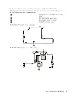


Table 38. Removal steps of antenna assembly (continued)
1
1
1
1
1
1
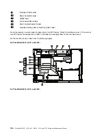
When installing:
Route the cables as shown in this figure. When you route the cables, make sure that they are not
subjected to any tension. Tension could cause the cables to be damaged by the cable guides, or a wire to be broken.
2
2
2
2
2
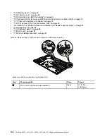
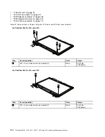
2050 Hinges, LCD panel, LCD cable, and LCD rear cover assembly
For access, remove these FRUs, in order:
•
“1010 Battery pack” on page 59
•
“1100 Wireless WAN slot cover and PCI Express Mini Card for wireless WAN” on page 73
•
“1110 Palm rest assembly with cables” on page 75
•
“1120 PCI Express Mini Card for wireless LAN” on page 78
•
“1160 Keyboard” on page 83
•
“1170 Keyboard bezel” on page 86
Chapter 8
.
Removing and replacing a FRU
111
Summary of Contents for ThinkPad L410
Page 1: ...ThinkPad SL410 L410 L412 SL510 L510 and L512 Hardware Maintenance Manual ...
Page 2: ......
Page 3: ...ThinkPad SL410 L410 L412 SL510 L510 and L512 Hardware Maintenance Manual ...
Page 8: ...vi ThinkPad SL410 L410 L412 SL510 L510 and L512 Hardware Maintenance Manual ...
Page 20: ...12 ThinkPad SL410 L410 L412 SL510 L510 and L512 Hardware Maintenance Manual ...
Page 21: ...Chapter 1 Safety information 13 ...
Page 29: ...Chapter 1 Safety information 21 ...
Page 32: ...24 ThinkPad SL410 L410 L412 SL510 L510 and L512 Hardware Maintenance Manual ...
Page 46: ...38 ThinkPad SL410 L410 L412 SL510 L510 and L512 Hardware Maintenance Manual ...
Page 62: ...54 ThinkPad SL410 L410 L412 SL510 L510 and L512 Hardware Maintenance Manual ...
Page 66: ...58 ThinkPad SL410 L410 L412 SL510 L510 and L512 Hardware Maintenance Manual ...
Page 126: ...118 ThinkPad SL410 L410 L412 SL510 L510 and L512 Hardware Maintenance Manual ...
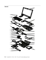
Page 239: ...1 3 4 5 6 7 8 9 2 Chapter 10 Parts list 231 ...
Page 280: ...272 ThinkPad SL410 L410 L412 SL510 L510 and L512 Hardware Maintenance Manual ...
Page 283: ......
Page 284: ...Part Number 60Y3635_02 Printed in China 1P P N 60Y3635_02 60Y3635_02 ...


