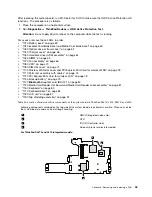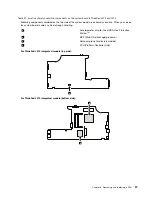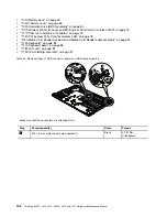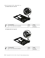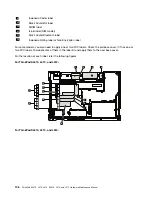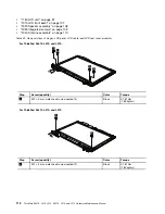
Table 35. Removal steps of LCD front bezel (continued)
2
2
2
2
2
2
2
2
2
2
2
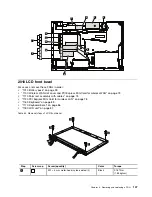
When installing:
Make sure that all the latches are attached firmly. Then secure the bezel with the screws.
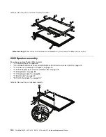
2020 Speaker assembly
For access, remove these FRUs in order:
•
“1010 Battery pack” on page 59
•
“1100 Wireless WAN slot cover and PCI Express Mini Card for wireless WAN” on page 73
•
“1110 Palm rest assembly with cables” on page 75
•
“1120 PCI Express Mini Card for wireless LAN” on page 78
•
“1160 Keyboard” on page 83
•
“1170 Keyboard bezel” on page 86
•
“1180 LCD unit” on page 87
•
“2010 LCD front bezel” on page 107
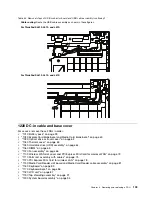
Table 36. Removal steps of speaker assembly
1
2
1
3
108
ThinkPad SL410, L410, L412, SL510, L510, and L512 Hardware Maintenance Manual
Summary of Contents for ThinkPad L410
Page 1: ...ThinkPad SL410 L410 L412 SL510 L510 and L512 Hardware Maintenance Manual ...
Page 2: ......
Page 3: ...ThinkPad SL410 L410 L412 SL510 L510 and L512 Hardware Maintenance Manual ...
Page 8: ...vi ThinkPad SL410 L410 L412 SL510 L510 and L512 Hardware Maintenance Manual ...
Page 20: ...12 ThinkPad SL410 L410 L412 SL510 L510 and L512 Hardware Maintenance Manual ...
Page 21: ...Chapter 1 Safety information 13 ...
Page 29: ...Chapter 1 Safety information 21 ...
Page 32: ...24 ThinkPad SL410 L410 L412 SL510 L510 and L512 Hardware Maintenance Manual ...
Page 46: ...38 ThinkPad SL410 L410 L412 SL510 L510 and L512 Hardware Maintenance Manual ...
Page 62: ...54 ThinkPad SL410 L410 L412 SL510 L510 and L512 Hardware Maintenance Manual ...
Page 66: ...58 ThinkPad SL410 L410 L412 SL510 L510 and L512 Hardware Maintenance Manual ...
Page 126: ...118 ThinkPad SL410 L410 L412 SL510 L510 and L512 Hardware Maintenance Manual ...
Page 239: ...1 3 4 5 6 7 8 9 2 Chapter 10 Parts list 231 ...
Page 280: ...272 ThinkPad SL410 L410 L412 SL510 L510 and L512 Hardware Maintenance Manual ...
Page 283: ......
Page 284: ...Part Number 60Y3635_02 Printed in China 1P P N 60Y3635_02 60Y3635_02 ...


