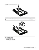
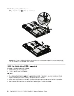
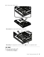

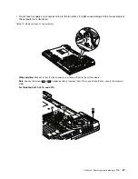
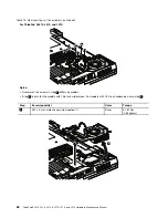
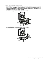
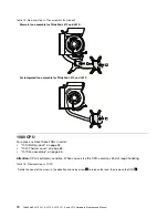


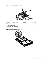
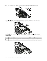
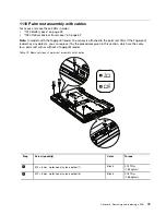
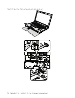
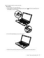


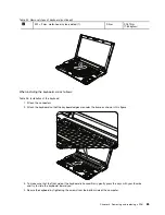


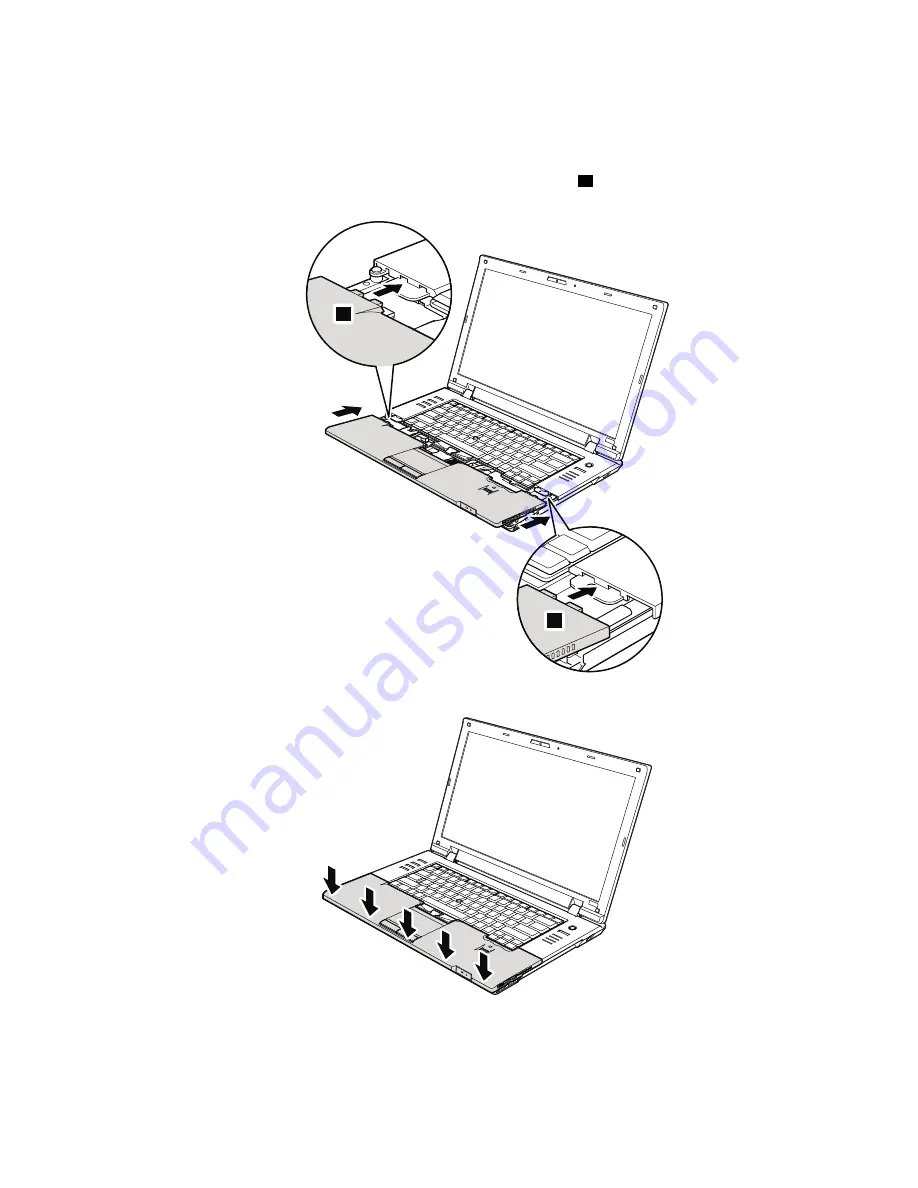
Table 20. Installation of palm rest assembly with cables
When installing:
1. Attach the cables to the system board firmly.
2. Attach the palm rest so that the two small projections of the palm rest (
a
) firmly fit into the guide holes of the
keyboard bezel as shown in this figure.
a
a
3. Push the front side of the palm rest until it clicks into place.
4. Close the LCD cover and turn the computer over. Then fasten the screws to secure the palm rest.
Chapter 8
.
Removing and replacing a FRU
77
Summary of Contents for ThinkPad L410
Page 1: ...ThinkPad SL410 L410 L412 SL510 L510 and L512 Hardware Maintenance Manual ...
Page 2: ......
Page 3: ...ThinkPad SL410 L410 L412 SL510 L510 and L512 Hardware Maintenance Manual ...
Page 8: ...vi ThinkPad SL410 L410 L412 SL510 L510 and L512 Hardware Maintenance Manual ...
Page 20: ...12 ThinkPad SL410 L410 L412 SL510 L510 and L512 Hardware Maintenance Manual ...
Page 21: ...Chapter 1 Safety information 13 ...
Page 29: ...Chapter 1 Safety information 21 ...
Page 32: ...24 ThinkPad SL410 L410 L412 SL510 L510 and L512 Hardware Maintenance Manual ...
Page 46: ...38 ThinkPad SL410 L410 L412 SL510 L510 and L512 Hardware Maintenance Manual ...
Page 62: ...54 ThinkPad SL410 L410 L412 SL510 L510 and L512 Hardware Maintenance Manual ...
Page 66: ...58 ThinkPad SL410 L410 L412 SL510 L510 and L512 Hardware Maintenance Manual ...
Page 126: ...118 ThinkPad SL410 L410 L412 SL510 L510 and L512 Hardware Maintenance Manual ...
Page 239: ...1 3 4 5 6 7 8 9 2 Chapter 10 Parts list 231 ...
Page 280: ...272 ThinkPad SL410 L410 L412 SL510 L510 and L512 Hardware Maintenance Manual ...
Page 283: ......
Page 284: ...Part Number 60Y3635_02 Printed in China 1P P N 60Y3635_02 60Y3635_02 ...


