


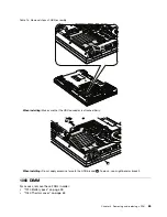

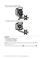


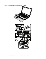


Table 14. Removal steps of DIMM
1
1
2
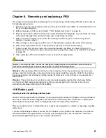
Note:
If only one DIMM is used on the computer you are servicing, the card must be installed in SLOT-0 (
a
: lower
slot), but not in SLOT-1 (
b
: upper slot).
b
a
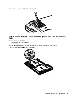
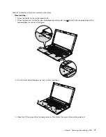
When installing:
Insert the notched end of the DIMM into the socket. Press the DIMM firmly, and pivot it until it
snaps into the place. Make sure that it is firmly fixed in the slot and does not move easily.
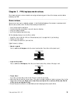
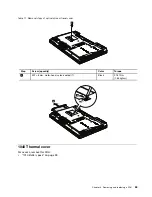
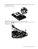
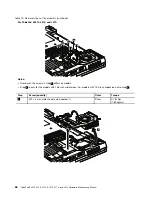
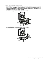
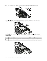
1070 Fan assembly
For access, remove these FRUs in order:
•
“1010 Battery pack” on page 59
•
“1040 Thermal cover” on page 63
Attention:
• Do
not
handle the fan roughly. Improper handling of the fan can cause distortion or deformation and
imperfect contact with components.
66
ThinkPad SL410, L410, L412, SL510, L510, and L512 Hardware Maintenance Manual
Summary of Contents for ThinkPad L410
Page 1: ...ThinkPad SL410 L410 L412 SL510 L510 and L512 Hardware Maintenance Manual ...
Page 2: ......
Page 3: ...ThinkPad SL410 L410 L412 SL510 L510 and L512 Hardware Maintenance Manual ...
Page 8: ...vi ThinkPad SL410 L410 L412 SL510 L510 and L512 Hardware Maintenance Manual ...
Page 20: ...12 ThinkPad SL410 L410 L412 SL510 L510 and L512 Hardware Maintenance Manual ...
Page 21: ...Chapter 1 Safety information 13 ...
Page 29: ...Chapter 1 Safety information 21 ...
Page 32: ...24 ThinkPad SL410 L410 L412 SL510 L510 and L512 Hardware Maintenance Manual ...
Page 46: ...38 ThinkPad SL410 L410 L412 SL510 L510 and L512 Hardware Maintenance Manual ...
Page 62: ...54 ThinkPad SL410 L410 L412 SL510 L510 and L512 Hardware Maintenance Manual ...
Page 66: ...58 ThinkPad SL410 L410 L412 SL510 L510 and L512 Hardware Maintenance Manual ...
Page 126: ...118 ThinkPad SL410 L410 L412 SL510 L510 and L512 Hardware Maintenance Manual ...
Page 239: ...1 3 4 5 6 7 8 9 2 Chapter 10 Parts list 231 ...
Page 280: ...272 ThinkPad SL410 L410 L412 SL510 L510 and L512 Hardware Maintenance Manual ...
Page 283: ......
Page 284: ...Part Number 60Y3635_02 Printed in China 1P P N 60Y3635_02 60Y3635_02 ...


