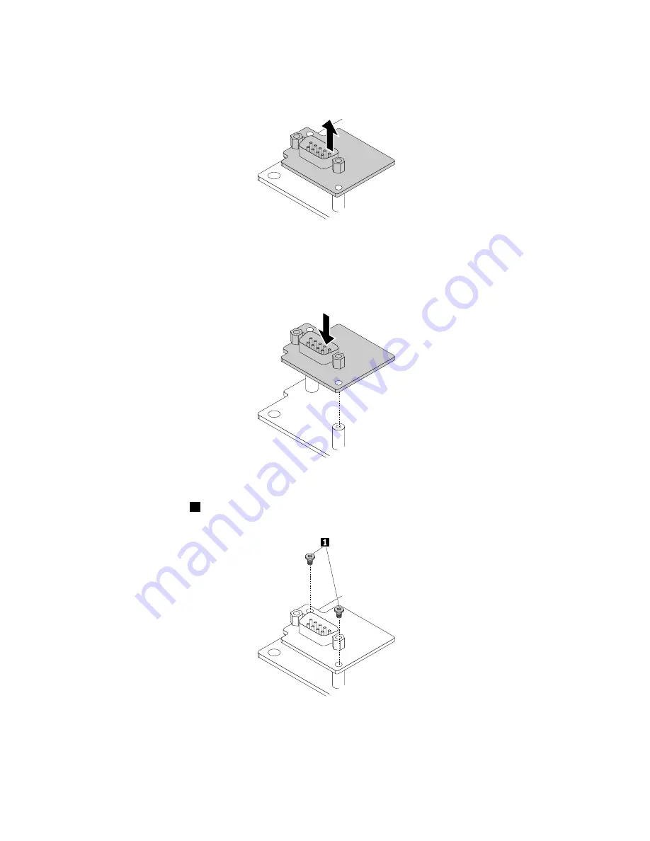
9. Lift the serial connector module to remove it from the system board.
Figure 49. Removing the serial connector module
10. Position the new serial connector module on the system board, so that the screw holes in the serial
connector module align with the corresponding mounting studs on the system board.
Figure 50. Installing the serial connector module
11. Install the two screws
1
to secure the serial connector module on the system board.
Figure 51. Installing the serial connector module screws
12. Connect the serial connector module cable to the serial connector module.
13. Install the system-board shield. See “Replacing the system-board shield” on page 66.
78
ThinkCentre M700z and M800z User Guide
Summary of Contents for ThinkCentre M700z
Page 1: ...ThinkCentre M700z and M800z User Guide Machine Types 10ET 10EU 10EV 10EW 10EY and 10F1 ...
Page 10: ...viii ThinkCentre M700z and M800z User Guide ...
Page 44: ...34 ThinkCentre M700z and M800z User Guide ...
Page 46: ...Figure 16 Kensington style cable lock for M700z 36 ThinkCentre M700z and M800z User Guide ...
Page 50: ...40 ThinkCentre M700z and M800z User Guide ...
Page 94: ...84 ThinkCentre M700z and M800z User Guide ...
Page 98: ...88 ThinkCentre M700z and M800z User Guide ...
Page 106: ...96 ThinkCentre M700z and M800z User Guide ...
Page 109: ...Appendix D China Energy Label Copyright Lenovo 2015 99 ...
Page 110: ...100 ThinkCentre M700z and M800z User Guide ...
Page 112: ...102 ThinkCentre M700z and M800z User Guide ...
Page 115: ......
Page 116: ......


