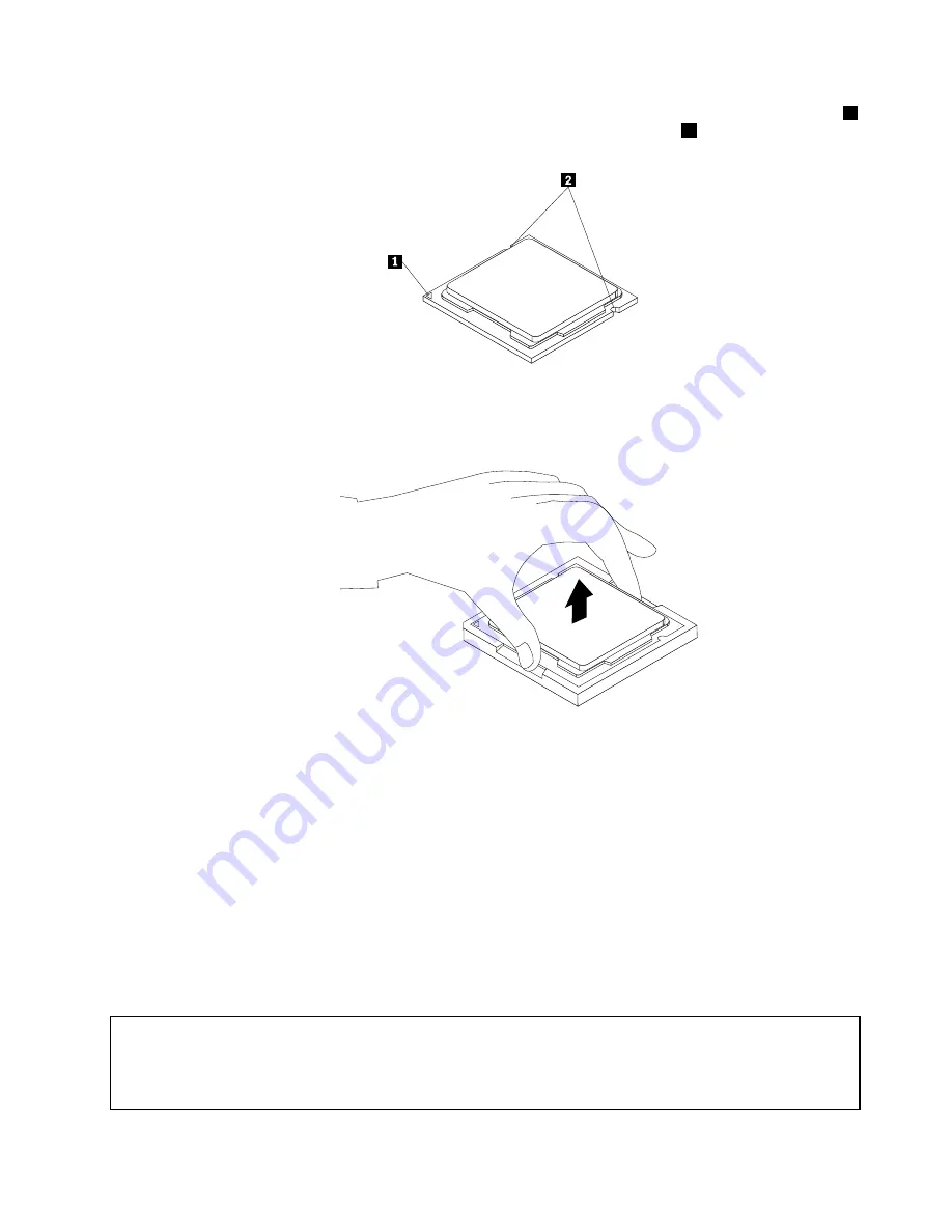
b. Note the orientation of the microprocessor in the socket. You can either look for the small triangle
1
on one corner of the microprocessor or note the orientation of the notches
2
on the microprocessor.
This is important when installing the new microprocessor on the system board.
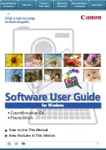
c. Touch only the edges of the microprocessor. Do not touch the gold contacts on the bottom.
d. Do not drop anything onto the microprocessor socket while it is exposed. The socket pins must be
kept as clean as possible.
Figure 21. Removing the microprocessor
6. Make sure that the small handle is in the raised position.
7. Remove the protective cover that protects the gold contacts of the new microprocessor.
8. Hold the new microprocessor by its sides and align the small triangle on one corner of the new
microprocessor with the corresponding small triangle on one corner of the microprocessor socket.
9. Lower the new microprocessor straight down into the microprocessor socket on the system board.
10. Lower the small handle to secure the new microprocessor in the socket.
11. Reinstall the heat sink and fan assembly. See “Replacing the heat sink and fan assembly” on page 84.
12. Reinstall any parts and reconnect any cables that have been removed or disconnected.
13. To complete the replacement, go to “Completing the parts replacement” on page 98.
Replacing the optical drive
Attention:
Do not open your computer or attempt any repair before reading and understanding the “Important safety information”
in the
ThinkCentre Safety and Warranty Guide
that came with your computer. To obtain a copy of the
ThinkCentre
Safety and Warranty Guide
, go to:
http://www.lenovo.com/support
Chapter 8
.
Installing or replacing hardware: 0041, 0107, 0163, and 7543
87
Summary of Contents for ThinkCentre A85
Page 2: ......
Page 8: ...vi ThinkCentre Hardware Maintenance Manual ...
Page 17: ...Chapter 2 Safety information 9 ...
Page 21: ...Chapter 2 Safety information 13 ...
Page 22: ...1 2 14 ThinkCentre Hardware Maintenance Manual ...
Page 23: ...Chapter 2 Safety information 15 ...
Page 29: ...Chapter 2 Safety information 21 ...
Page 33: ...Chapter 2 Safety information 25 ...
Page 40: ...32 ThinkCentre Hardware Maintenance Manual ...
Page 74: ...66 ThinkCentre Hardware Maintenance Manual ...
Page 108: ...100 ThinkCentre Hardware Maintenance Manual ...
Page 148: ...140 ThinkCentre Hardware Maintenance Manual ...
Page 243: ...Windows Vista Business 32 Recovery CD CRU MT 7548 Chapter 10 FRU lists 235 ...
Page 244: ...236 ThinkCentre Hardware Maintenance Manual ...
Page 248: ...240 ThinkCentre Hardware Maintenance Manual ...
Page 257: ......
Page 258: ...Part Number 0A23326 Printed in USA 1P P N 0A23326 0A23326 ...


