6. Carefully check the four corners of the socket cover to make sure that the cover is secured in the
microprocessor socket.
7. Lower the microprocessor retainer and then lower the lever to secure the retainer. Make sure the
lever is locked into position.
8. Follow any additional instructions included with the replacement part you received.
Note:
If your system board has two microprocessor sockets, be sure to install a socket cover for each
microprocessor socket.
Completing the parts replacement
After completing the installation or replacement for all parts, you need to reinstall the computer cover
and reconnect cables.
To reinstall the computer cover and reconnect cables to your computer, do the following:
1. Make sure that all components have been reassembled correctly and that no tools or loose screws are
left inside your computer. See “Locating components” on page 103 for the locations of the various
components in your computer.
2. Make sure that all the internal cables are routed properly to avoid interference with lowering the drive bay
assembly and closing the computer cover. Keep the cables clear of the hinges and sides of the chassis.
3. Lower the drive bay assembly. See “Accessing the system board components and drives” on page 109.
4. If you have removed the front bezel, reinstall it. See “Removing and reinstalling the front bezel” on
page 108.
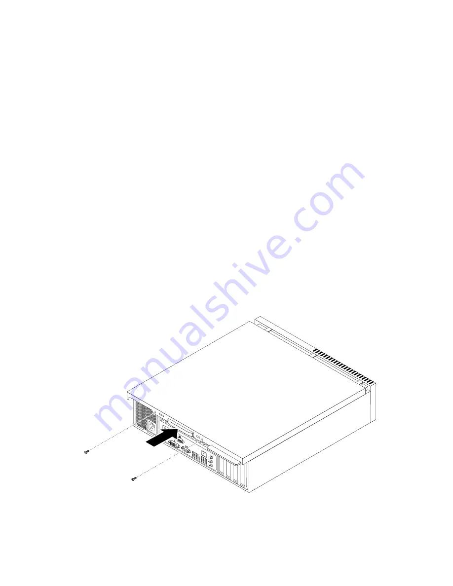
5. Position the computer cover on the chassis so that the rail guides on the computer cover engage the
rails on the chassis. Then, slide the computer cover to the front of the computer until it snaps into
position and is closed. Then, install the two screws to secure the computer cover.
Figure 78. Reinstalling the computer cover
6. Lock the computer cover if you have a computer cover lock.
138
ThinkCentre Hardware Maintenance Manual
Summary of Contents for ThinkCentre A85
Page 2: ......
Page 8: ...vi ThinkCentre Hardware Maintenance Manual ...
Page 17: ...Chapter 2 Safety information 9 ...
Page 21: ...Chapter 2 Safety information 13 ...
Page 22: ...1 2 14 ThinkCentre Hardware Maintenance Manual ...
Page 23: ...Chapter 2 Safety information 15 ...
Page 29: ...Chapter 2 Safety information 21 ...
Page 33: ...Chapter 2 Safety information 25 ...
Page 40: ...32 ThinkCentre Hardware Maintenance Manual ...
Page 74: ...66 ThinkCentre Hardware Maintenance Manual ...
Page 108: ...100 ThinkCentre Hardware Maintenance Manual ...
Page 148: ...140 ThinkCentre Hardware Maintenance Manual ...
Page 243: ...Windows Vista Business 32 Recovery CD CRU MT 7548 Chapter 10 FRU lists 235 ...
Page 244: ...236 ThinkCentre Hardware Maintenance Manual ...
Page 248: ...240 ThinkCentre Hardware Maintenance Manual ...
Page 257: ......
Page 258: ...Part Number 0A23326 Printed in USA 1P P N 0A23326 0A23326 ...


