6.
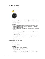
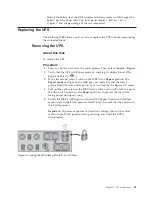
Wait 30 seconds for the UPS to stop functioning. Check the UPS display panel
to verify that the UPS is not functional.
7.
Remove the access cover on the terminal block cover and use a voltmeter to
ensure that hazardous voltage is no longer present.
Important:
Proceed only when no hazardous voltage is present on any
terminal.
8.
Unlock the conduit from the UPS terminal block cover. Then, loosen the set
screws holding the cable wires in the terminal block, and remove the cables.
9.
Connect the just-exposed wires together to help prevent exposure to
hazardous voltage.
10.
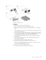
Remove the UPS battery pack by following the steps in “Replacing the
internal battery pack” on page 48.
Results
The UPS can be removed and replaced.
Important:
When UPS is not connected to the MBP, ensure that the MBP manual
Bypass switch is locked. Do not manipulate the switch unless the UPS is connected
to the MBP.
Returning to normal operation
About this task
After performing maintenance on the UPS, follow these steps to put the UPS back
into service and resume normal operation.
Procedure
1.
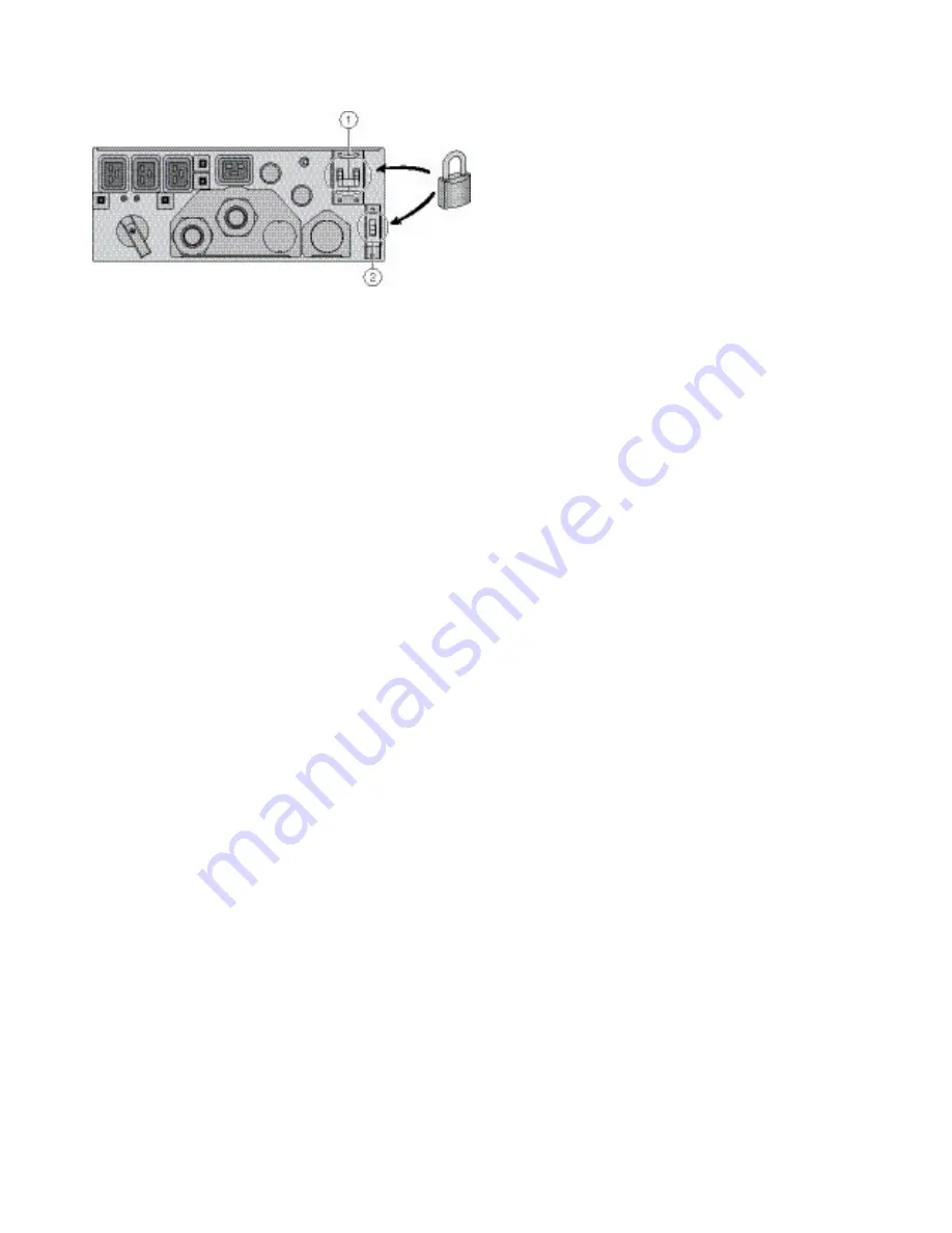
Ensure that the locks are still in place, holding the MBP's UPS Input switch
and UPS Bypass Input switch (3Phase model only) in the
0
(off) position.
Important:
To prevent exposure to hazardous voltage, the switches must
remain in the
0
(off) position during servicing and while the UPS is
disconnected.
2.
Connect the UPS to the MBP.
3.
Remove the connection between the exposed wires, insert them through the
terminal cover into the terminal block, and tighten the set screws. Be sure to
connect the UPS AC input cable (blue conduit) and UPS output cable (red
conduit) properly. See “HotSwap MBP connection” on page 30 for details.
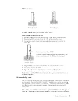
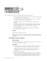
Figure 12. Locking the UPS Input switch and UPS Bypass Input switch (8/11k VA 3Phase)
52
Installation and User's Guide
Summary of Contents for RT11.0VA
Page 2: ......
Page 18: ...xvi Installation and User s Guide ...
Page 22: ...4 Installation and User s Guide ...
Page 86: ...68 Installation and User s Guide ...
Page 98: ...80 Installation and User s Guide ...
Page 100: ...82 Installation and User s Guide ...
Page 101: ......
Page 102: ...Part Number 00WA361 Printed in USA 1P P N 00WA361 ...

