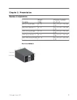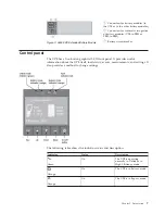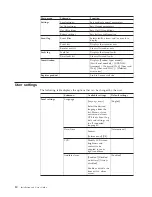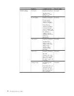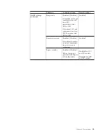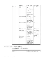
Figure 3. 5594-9BX Extended Battery Module
Connectors for battery modules (to
the UPS or to the other battery modules)
Connectors for automatic recognition
of battery modules (UPS-to-EBM or
EBM-to-EBM)
Battery circuit breaker
Control panel
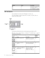
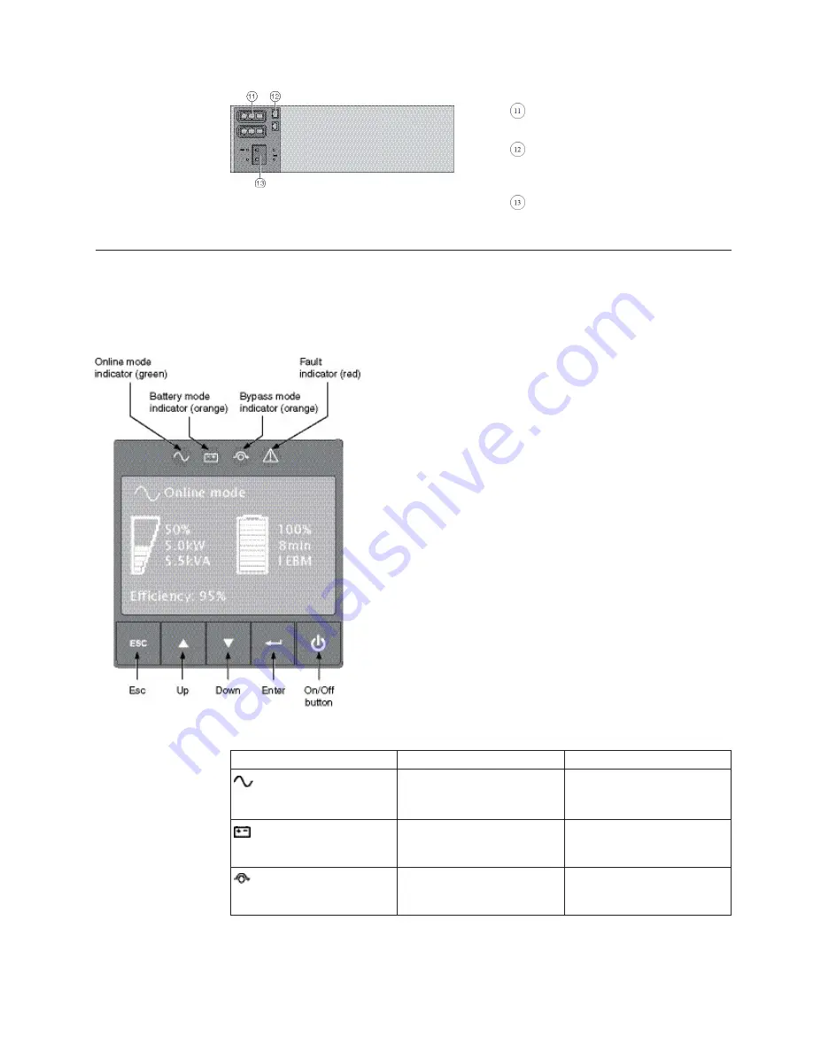
The UPS has a five-button graphical LCD front panel. It provides useful
information about the UPS itself, load status, events, measurements, and settings. It
also provides a method to change settings.
The following table shows the indicator status and description:
Indicator
Status
Description
Green
On
The UPS is operating
normally in Online or in
High Efficiency mode.
Orange
On
The UPS is in Battery mode.
Orange
On
The UPS is in Bypass mode.
Chapter 2. Presentation
7
Summary of Contents for RT11.0VA
Page 2: ......
Page 18: ...xvi Installation and User s Guide ...
Page 22: ...4 Installation and User s Guide ...
Page 86: ...68 Installation and User s Guide ...
Page 98: ...80 Installation and User s Guide ...
Page 100: ...82 Installation and User s Guide ...
Page 101: ......
Page 102: ...Part Number 00WA361 Printed in USA 1P P N 00WA361 ...


