


6. Remove the two screws that secure the computer handle, and then remove the computer handle
as shown.
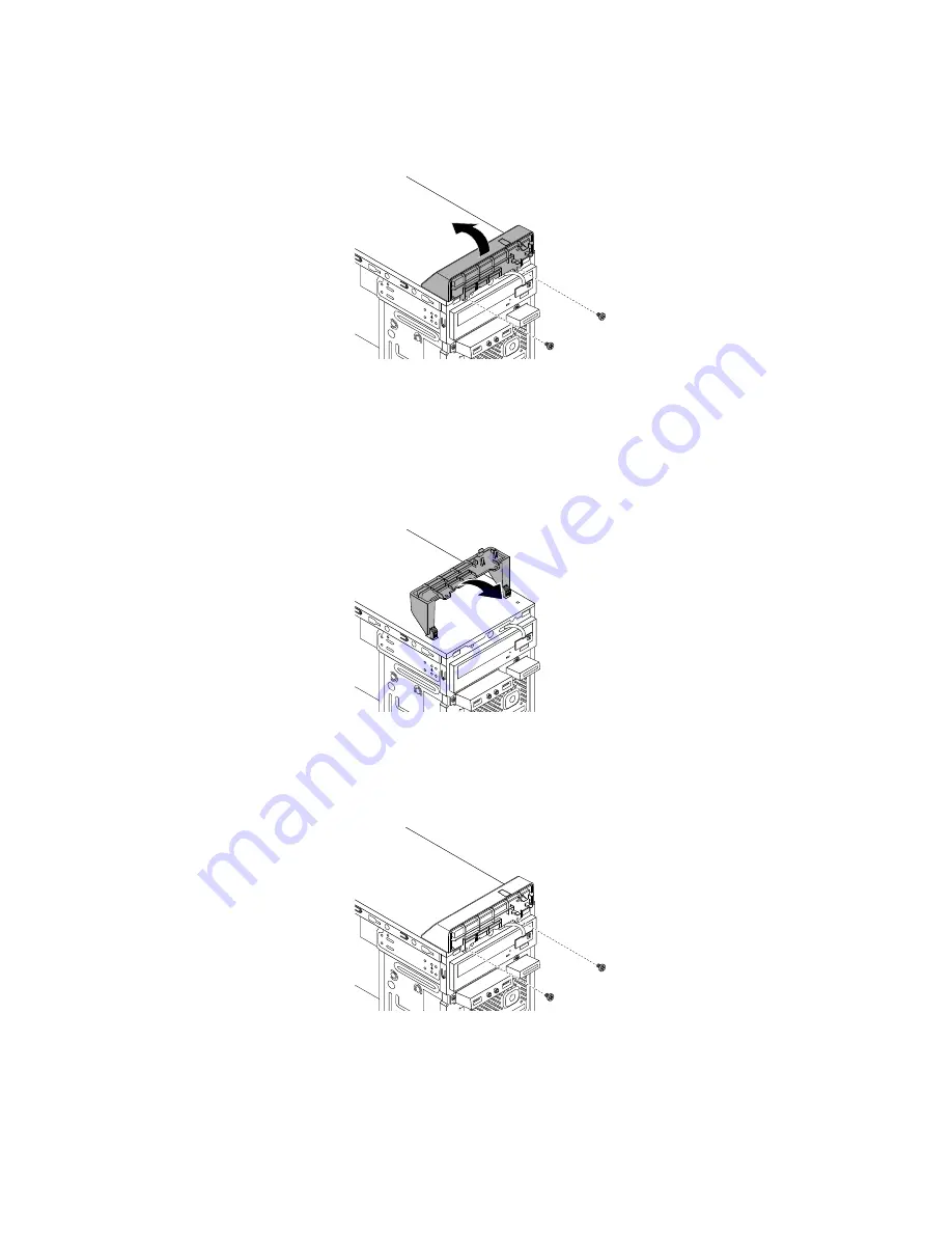
Figure 17. Removing computer handle
7. Insert the two ends of the computer handle into the corresponding holes in the chassis, and then
pivot the computer handle as shown so that the two screw holes in the computer handle align with
the corresponding screw holes in the chassis.
Figure 18. Installing the computer handle
8. Install the two screws to secure the computer handle.
Figure 19. Installing the computer handle screws
9. Install the power button board. See “Replacing the power button board” on page 85.
10. Install the front bezel. See “Replacing the front bezel” on page 83.
88
Lenovo S200 Hardware Maintenance Manual
Summary of Contents for IdeaPad S200
Page 1: ...Lenovo S200 Hardware Maintenance Manual Machine Types 10HQ and 10HR ...
Page 6: ...iv Lenovo S200 Hardware Maintenance Manual ...
Page 14: ...8 Lenovo S200 Hardware Maintenance Manual ...
Page 18: ...12 Lenovo S200 Hardware Maintenance Manual ...
Page 19: ...1 2 Chapter 1 Read this first Important safety information 13 ...
Page 20: ...1 2 14 Lenovo S200 Hardware Maintenance Manual ...
Page 25: ...1 2 Chapter 1 Read this first Important safety information 19 ...
Page 26: ...1 2 20 Lenovo S200 Hardware Maintenance Manual ...
Page 29: ...Chapter 1 Read this first Important safety information 23 ...
Page 46: ...40 Lenovo S200 Hardware Maintenance Manual ...
Page 58: ...52 Lenovo S200 Hardware Maintenance Manual ...
Page 62: ...56 Lenovo S200 Hardware Maintenance Manual ...
Page 68: ...62 Lenovo S200 Hardware Maintenance Manual ...
Page 80: ...74 Lenovo S200 Hardware Maintenance Manual ...
Page 120: ...114 Lenovo S200 Hardware Maintenance Manual ...
Page 128: ...122 Lenovo S200 Hardware Maintenance Manual ...
Page 131: ...Appendix D China Energy Label Copyright Lenovo 2015 2016 125 ...
Page 132: ...126 Lenovo S200 Hardware Maintenance Manual ...
Page 134: ...128 Lenovo S200 Hardware Maintenance Manual ...
Page 137: ......
Page 138: ......


