Lenovo 30BA Hardware Maintenance Manual Download Page 170

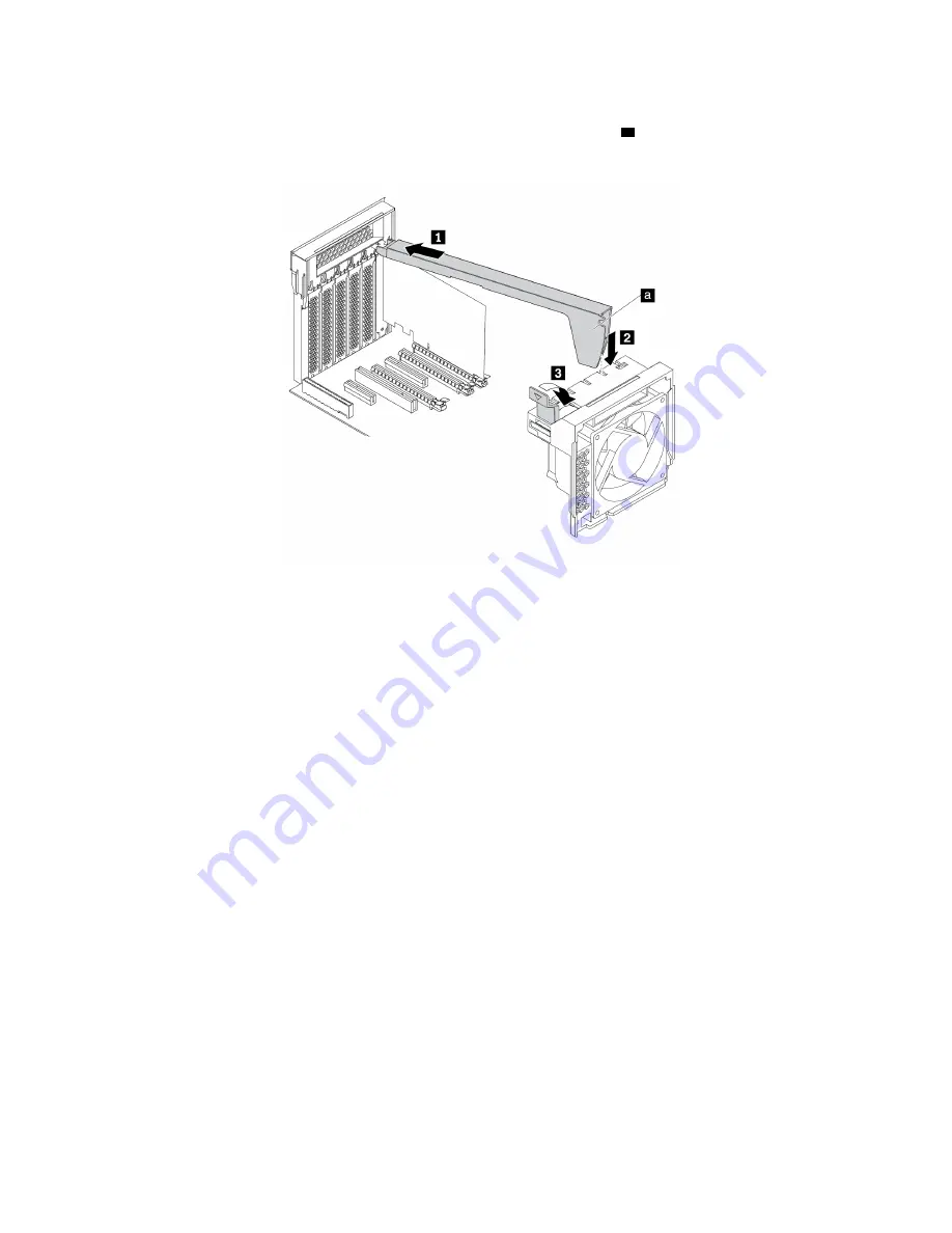
6.  To install a PCIe card retainer, insert the corresponding end of the PCIe card retainer into the gaps in the 

PCIe card latch as shown. Pivot the retainer downward to insert the part 

into the corresponding slot in 

the front fan assembly. Then, pivot the tab on the front fan assembly to close the latch inside. 

Figure 124. Installing the PCIe card retainer

What to do next: 

•  To work with another piece of hardware, go to the appropriate section.

•  To complete the installation or replacement, go to “Completing the parts replacement” on page 220.

Full-length PCIe card

Attention:

Do not open your computer or attempt any repair before reading and understanding the Chapter 

1 “Read this first: Important safety information” on page 1.

Your computer comes with the following combinations: one standard PCI card slot, one PCIe 3.0 x4 card 
slot, one PCIe 3.0 x8 card slot, and three PCIe 3.0 x16 card slots.

To remove or install a full-length PCIe card, do the following: 

1.  Prepare your computer. See “Preparing your computer and removing the computer cover” on page 103.

2.  Lay the computer on its side for easier access to the system board.

164

P720 Hardware Maintenance Manual

Summary of Contents for 30BA

Page 1: ...P720 Hardware Maintenance Manual Machine Types 30BA 30BB and 30BU ...

Page 2: ...afety information on page 1 and Appendix G Notices on page 243 First Edition October 2017 Copyright Lenovo 2017 LIMITED AND RESTRICTED RIGHTS NOTICE If data or software is delivered pursuant to a General Services Administration GSA contract use reproduction or disclosure is subject to restrictions set forth in Contract No GS 35F 05925 ...

Page 3: ...nance 57 Basic maintenance tips 57 Good maintenance practices 58 Keeping your computer current 58 Moving your computer 59 Chapter 5 Security 61 Locking your computer 61 Locking the computer cover 61 Attaching a Kensington style cable lock 63 Viewing and changing security settings in the Setup Utility program 63 Using passwords and Windows accounts 63 Using fingerprint authentication 64 Using the c...

Page 4: ...orage enclosure 107 Device in the multi drive conversion kit 114 Flex bay bracket 125 Cover presence switch 127 3 5 inch storage drive in the storage drive bay 129 2 5 inch storage drive in the storage drive bay 133 2 5 inch storage drive with a converter in the storage drive bay 138 M 2 solid state drive 146 Power supply assembly 156 PCIe card 158 Full length PCIe card 164 Super capacitor module ...

Page 5: ... 234 Appendix D WEEE and recycling information 235 Important WEEE information 235 Recycling information for Japan 235 Recycling information for Brazil 236 Battery recycling information for Taiwan 236 Battery recycling information for the European Union 237 Appendix E Restriction of Hazardous Substances RoHS Directive 239 Appendix F ENERGY STAR model information 241 Appendix G Notices 243 Trademark...

Page 6: ... tests to troubleshoot problems Important This manual is intended only for trained service technicians who are familiar with ThinkStation computers Use this manual along with the advanced diagnostic tests to troubleshoot problems effectively Before servicing a ThinkStation computer be sure to read and understand Chapter 1 Read this first Important safety information on page 1 ...

Page 7: ...ower cord connectors are securely and completely plugged into receptacles Do not use any power adapter that shows corrosion at the ac input pins or shows signs of overheating such as deformed plastic at the ac input or anywhere on the power adapter Do not use any power cords where the electrical contacts on either end show signs of corrosion or overheating or where the power cord appears to have b...

Page 8: ...the skin Before you open the computer cover turn off the computer disconnect power and wait approximately 10 minutes for the components to cool Electrical safety CAUTION Electrical current from power telephone and communication cables can be hazardous To avoid personal injury or equipment damage disconnect the attached power cords telecommunication systems networks and modems before you open the c...

Page 9: ...disconnected from a circuit First check that it has been powered off Always look carefully for possible hazards in your work area Examples of these hazards are moist floors nongrounded power extension cables power surges and missing safety grounds Do not touch live electrical circuits with the reflective surface of a plastic dental mirror The surface is conductive such touching can cause personal ...

Page 10: ...moved or tampered with Handling electrostatic discharge sensitive devices Any computer part containing transistors or integrated circuits ICs should be considered sensitive to electrostatic discharge ESD ESD damage can occur when there is a difference in charge between objects Protect against ESD damage by equalizing the charge so that the machine the part the work mat and the person handling the ...

Page 11: ...n Spanish DANGER Electrical current from power telephone and communication cables is hazardous To avoid a shock hazard Do not connect or disconnect any cables or perform installation maintenance or reconfiguration of this product during an electrical storm Connect all power cords to a properly wired and grounded electrical outlet Connect to properly wired outlets any equipment that will be attache...

Page 12: ...ot Throw or immerse into water Heat to more than 100 C 212 F Repair or disassemble Dispose of the battery as required by local ordinances or regulations CAUTION When laser products such as CD ROMs DVD ROM drives fiber optic devices or transmitters are installed note the following Do not remove the covers Removing the covers of the laser product could result in exposure to hazardous laser radiation...

Page 13: ...and the power switch on the power supply do not turn off the electrical current supplied to the device The device also might have more than one power cord To remove all electrical current from the device ensure that all power cords are disconnected from the power source 1 2 Chapter 1 Read this first Important safety information 7 ...

Page 14: ...8 P720 Hardware Maintenance Manual ...

Page 15: ... 18 kg 37 lb 32 kg 70 5 lb 55 kg 121 2 lb 1 2 Chapter 1 Read this first Important safety information 9 ...

Page 16: ...cte os cabos conforme descrito na tabela apresentada a seguir ao instalar mover ou abrir tampas deste produto ou de dispositivos conectados Para Conectar Para Desconectar 1 DESLIGUE Tudo 2 Primeiramente conecte todos os cabos aos dispositivos 3 Conecte os cabos de sinal aos conectores 4 Conecte os cabos de alimentação às tomadas 5 LIGUE os dispositivos 1 DESLIGUE Tudo 2 Primeiramente remova os cab...

Page 17: ... laser integrado da Classe 3A ou da Classe 3B Observe o seguinte Radiação a laser quando aberto Não olhe diretamente para o feixe a olho nu ou com instrumentos ópticos e evite exposição direta ao feixe 18 kg 37 lb 32 kg 70 5 lb 55 kg 121 2 lb CUIDADO Utilize procedimentos de segurança para levantar equipamentos CUIDADO O botão de controle de alimentação do dispositivo e o botão para ligar desligar...

Page 18: ...12 P720 Hardware Maintenance Manual ...

Page 19: ...1 2 Chapter 1 Read this first Important safety information 13 ...

Page 20: ...14 P720 Hardware Maintenance Manual ...

Page 21: ...qu une seule main pour connecter ou déconnecter les câbles d interface Ne mettez jamais un équipement sous tension en cas d incendie ou d inondation ou en présence de dommages matériels Avant de retirer les carters de l unité mettez celle ci hors tension et déconnectez ses cordons d alimentation ainsi que les câbles qui la relient aux réseaux aux systèmes de télécommunication et aux modems sauf in...

Page 22: ...appropriée Ne pas la jeter à l eau l exposer à des températures supérieures à 100 C chercher à la réparer ou à la démonter Ne pas mettre la pile à la poubelle Pour la mise au rebut se reporter à la réglementation en vigueur ATTENTION Si des produits à laser tels que des unités de CD ROM de DVD ROM des unités à fibres optiques ou des émetteurs sont installés prenez connaissance des informations sui...

Page 23: ...en Aus Sicherheitsgründen Bei Gewitter an diesem Gerät keine Kabel anschließen oder lösen Ferner keine Installations Wartungs oder Rekonfigurationsarbeiten durchführen Gerät nur an eine Schutzkontaktsteckdose mit ordnungsgemäß geerdetem Schutzkontakt anschließen Alle angeschlossenen Geräte ebenfalls an Schutzkontaktsteckdosen mit ordnungsgemäß geerdetem Schutzkontakt anschließen Die Signalkabel na...

Page 24: ...umbatterie nur durch eine Batterie mit der Teilenummer 45C1566 oder eine gleichwertige vom Hersteller empfohlene Batterie ersetzen Enthält das System ein Modul mit einer Lithiumbatterie dieses nur durch ein Modul desselben Typs und von demselben Hersteller ersetzen Die Batterie enthält Lithium und kann bei unsachgemäßer Verwendung Handhabung oder Entsorgung explodieren Die Batterie nicht mit Wasse...

Page 25: ... Maschine beachten ACHTUNG Mit dem Netzschalter an der Einheit und am Netzteil wird die Stromversorgung für die Einheit nicht unterbrochen Die Einheit kann auch mit mehreren Netzkabeln ausgestattet sein Um die Stromversorgung für die Einheit vollständig zu unterbrechen müssen alle zum Gerät führenden Netzkabel vom Netz getrennt werden 1 2 Chapter 1 Read this first Important safety information 19 ...

Page 26: ...20 P720 Hardware Maintenance Manual ...

Page 27: ...La corrente elettrica proveniente dai cavi di alimentazione del telefono e di comunicazione può essere pericolosa Per evitare il rischio di scosse elettriche Chapter 1 Read this first Important safety information 21 ...

Page 28: ...recchiature 2 Innanzitutto collegare tutti i cavi alle unità 3 Collegare i cavi di segnale ai connettori 4 Collegare i cavi di alimentazione alla presa 5 Accendere l unità 1 SPEGNERE le apparecchiature 2 Innanzitutto rimuovere i cavi di alimentazione dalla presa 3 Rimuovere i cavi di segnale dai connettori 4 Rimuovere tutti i cavi dalle unità ATTENZIONE Quando si sostituisce la batteria al litio u...

Page 29: ... Aprendo l unità vengono emesse radiazioni laser Non fissare il fascio non guardarlo direttamente con strumenti ottici ed evitare l esposizione al fascio 18 kg 32 kg 55 kg ATTENZIONE Prestare attenzione nel sollevare l apparecchiatura ATTENZIONE Il pulsante di controllo dell alimentazione presente sull unità e l interruttore dell alimentatore non disattivano l alimentazione corrente fornita all un...

Page 30: ...24 P720 Hardware Maintenance Manual ...

Page 31: ...ntenimiento o reconfiguración de este producto durante una tormenta eléctrica Conecte todos los cables de alimentación a tomas de corriente debidamente cableadas y conectadas a tierra Cualquier equipo que se conecte a este producto también debe conectarse a tomas de corriente debidamente cableadas Siempre que sea posible utilice una sola mano para conectar o desconectar los cables de señal Chapter...

Page 32: ...s dispositivos PRECAUCIÓN Cuando sustituya una batería de litio utilice solamente una batería número de pieza 45C1566 u otra de tipo equivalente recomendada por el fabricante Si su sistema dispone de un módulo que contiene una batería de litio reemplácelo sólo con el mismo tipo de módulo del mismo fabricante La batería contiene litio y puede explotar si no se utiliza manipula o desecha correctamen...

Page 33: ...ocedimientos seguros al levantar el equipo PRECAUCIÓN El botón de control de alimentación del dispositivo y el interruptor de alimentación de la fuente de alimentación no desconectan la corriente eléctrica suministrada al dispositivo Además el dispositivo podría tener más de un cable de alimentación Para suprimir toda la corriente eléctrica del dispositivo asegúrese de que todos los cables de alim...

Page 34: ...28 P720 Hardware Maintenance Manual ...

Page 35: ...models 2 Power button 3 Power indicator 4 Storage drive activity indicator 5 Signal diagnostic LED indicator 6 SD card slot 7 Photoelectric sensor 8 USB 3 0 connectors 3 9 Always On USB 3 0 connector 10 Headset connector Note The orientation of the ThinkStation logo plate on the front of your computer is adjustable When you lay the computer on its side you can slightly pull out the logo plate Turn...

Page 36: ...card into the slot to access the data on the card 7 Photoelectric sensor This sensor receives the flash light sent by the Lenovo PC Diagnostics application installed in the smartphone Then the photoelectric sensor triggers the computer to send the tune of the detected error to the smartphone for users to decode the error 8 USB 3 0 connector 3 Use this connector to attach a USB compatible device su...

Page 37: ... from the illustration Figure 2 Rear view 1 Audio line out connector 2 Microphone connector 3 Optional serial connector 4 PS 2 keyboard connector 5 USB 2 0 connectors 2 6 USB 3 0 connectors 4 7 PCI PCIe card area 8 Power cord connector 9 Security lock slot 10 Key nest slots 11 Ethernet connectors 2 12 Padlock loop 13 PS 2 mouse connector 14 Audio line in connector Chapter 2 Product overview 31 ...

Page 38: ...or to attach a high performance monitor a direct drive monitor or other compatible devices The Mini DisplayPort connector is a miniaturized version of a DisplayPort connector 1 Audio line out connector The audio line out connector is used to send audio signals from the computer to external devices such as headphones 2 Microphone connector Use this connector to attach a microphone to your computer ...

Page 39: ...Ethernet connectors 2 Connect an Ethernet cable for a local area network LAN Note To operate the computer within Federal Communications Commission FCC Class B limits use a Category 5 Ethernet cable 12 Padlock loop Connect a padlock to secure your computer For more information see Locking the computer cover on page 61 13 PS 2 mouse connector Use this connector to attach a PS 2 mouse a trackball or ...

Page 40: ... modules 3 Cover presence switch also called intrusion switch 4 Flex bays 5 Front fan assembly 6 Storage drives or a storage drive bay cover 7 Storage drives 8 M 2 solid state drive holder 9 Power supply assembly 10 Memory air baffles 11 PCI PCIe card 12 Rear fan assembly Configuration varies by computer models Major FRUs and CRUs The following illustration shows the locations of the major FRUs an...

Page 41: ...Figure 4 Major FRUs and CRUs Chapter 2 Product overview 35 ...

Page 42: ...RU 1 Rear fan assembly Yes No 2 Heat sink and fan assembly 2 available on some models No No 3 Heat sink and fan assembly 1 No No 4 Internal speaker No No 5 Cover presence switch intrusion switch Yes No 6 Flex bay bracket Yes No 7 Slim optical drive adapter available on some models Yes No 8 Multi drive conversion kit available on some models Yes No 9 Optical drive available on some models Yes No 10...

Page 43: ...e models No Yes 29 Coin cell battery No Yes 30 System board No No 31 Memory modules No Yes 32 Microprocessor No No a Lenovo factory recovery USB key available on some models No No b Lenovo recovery disc set available on some models No No c Miscellaneous parts kits No No d Power cord Yes No e Keyboard available on some models Yes No f Mouse available on some models Yes No For detailed FRU informati...

Page 44: ...sor 1 memory slot 4 13 Microprocessor 1 memory slot 3 14 Microprocessor 1 memory slot 5 15 Microprocessor 1 memory slot 1 16 Thermal sensor connector 17 Cover presence switch connector intrusion switch connector 18 Microprocessor 1 19 Microprocessor fan connector 1 20 Blind connect assembly BCA 3 connector 21 M 2 solid state drive slot 1 22 M 2 solid state drive slot 2 23 VROC header 24 Trusted cr...

Page 45: ...B 3 0 connector 1 44 15 in 1 card reader connector 45 SATA 4 connector 46 SATA 3 connector 47 SATA 2 connector 48 SATA 1 connector 49 Power supply connector 50 SATA 5 connector 51 eSATA SATA connector 52 PCIe 3 0 x4 card slot 6 53 PCI card slot 5 54 PCIe 3 0 x16 card slot 4 55 Clear CMOS Recovery jumper 56 PCIe 3 0 x8 card slot 3 57 PCIe 3 0 x16 card slot 2 58 PCIe 3 0 x16 card slot 1 59 Coin cell...

Page 46: ...pter 9 Hardware removal and installation on page 103 for instructions on how to remove or install internal storage drives for your computer The following illustration shows the locations of the storage drive bays Note The computer hardware might look slightly different from the illustration Figure 6 Storage drive bay locations 1 Card reader for an SD card 2 Flex bays 2 3 Optional storage drive bay...

Page 47: ...h as hard disk drive solid state drive or hybrid drive Slim optical drive Optical drive Slim optical drive adapter 3 Optional storage drive bays 2 You can install hard disk drives solid state drives or hybrid drives in the storage drive bays Note If you want to install storage drives into the 3 optional storage drive bays contact the Lenovo Customer Support Center for help 4 Storage drive bays 2 Y...

Page 48: ...rmation such as microprocessor and memory information about your computer do the following 1 Click the Start button to open the Start menu 2 Depending on your Microsoft Windows operating system version do one of the following For Windows 7 Right click Computer and then click Properties For Windows 10 Click Settings System About To view detailed information about the devices such as the optical dri...

Page 49: ...age For Windows 10 Right click the Start button to open the Start context menu 2 Click Disk Management and follow the instructions on the screen Video features PCIe 3 0 x16 card slots on the system board for a discrete graphics card Video connectors on a discrete graphics card DVI connector available on some models DisplayPort connector available on some models Mini DisplayPort connector available...

Page 50: ...mation includes the processor type installation date attached printers and other peripherals power sources and maintenance history ErP LPS compliance mode The energy related products directive ErP lowest power state LPS compliance mode reduces the consumption of electricity when your computer is in sleep or off mode For more information see Enabling or disabling the ErP LPS compliance mode on page...

Page 51: ...trumentation WMI Windows Management Instrumentation is a set of extensions to the Windows Driver Model It provides an operating system interface through which instrumented components provide information and notification Security features Ability to enable and disable a device Ability to enable and disable USB connectors individually Antivirus program BIOS passwords and Windows accounts to deter un...

Page 52: ...ending on your computer model some of the Lenovo programs might be ready to be installed so you must install them manually Then you can access and use these programs To access a program on your computer do one of the following From Windows Search 1 Depending on your Windows version do one of the following For Windows 7 Click the Start button to open the Start menu and then type the program name in...

Page 53: ...e Fingerprint Software Windows 7 The Fingerprint Manager Pro or ThinkVantage Fingerprint Software program enables you to use a fingerprint reader The integrated fingerprint reader provided on some keyboards enables you to enroll your fingerprint and associate it with your power on password hard disk password and Windows password As a result fingerprint authentication can replace passwords and enab...

Page 54: ...Vantage Tools program provides easy access to various tools to help your work more easily and securely Recovery Media Windows 7 The Recovery Media program enables you to restore the contents of the hard disk drive to the factory default settings System Update Windows 7 The System Update program provides regular access to the system updates for your computer such as device driver updates software u...

Page 55: ...fication area add the icon to the notification area See the Windows help system 2 Follow the instructions on the screen and the hover text to adjust the volume mute the speaker or unmute the speaker Using a disc This section provides instructions on how to use a disc and the optical drive Guidelines about using the optical drive When using the optical drive follow these guidelines Do not place the...

Page 56: ... optical drive The tray slides out of the drive 2 Carefully remove the disc from the tray 3 Press the eject close button again or gently push the tray forward to close the tray Note If the tray does not slide out of the drive when you press the eject close button turn off your computer Then insert a straightened paper clip into the emergency eject hole adjacent to the eject close button Use the em...

Page 57: ...he Ethernet connector Connecting to a wireless LAN You can connect your computer to a wireless LAN without the use of an Ethernet cable but by means of radio waves only Note The wireless LAN feature is available only on some models To establish a wireless LAN connection do the following 1 Ensure that a wireless LAN is available and the wireless LAN feature on your computer is working 2 Click the w...

Page 58: ...distance of about 10 m 32 8 ft from your computer 2 Click the Bluetooth icon in the Windows notification area on the taskbar Then click Add a Device and follow the instructions on the screen Note If the Bluetooth icon is not displayed in the Windows notification area add the icon to the notification area See the Windows help system 52 P720 Hardware Maintenance Manual ...

Page 59: ...ing an antiglare filter placed over the screen might be helpful However these filters might affect the clarity of the image on the screen try them only after you have exhausted other methods of reducing glare Air circulation Your computer produces heat The computer has a fan that pulls in fresh air and forces out hot air through the air vents Blocking the air vents can cause overheating which migh...

Page 60: ... who have hearing vision and mobility limitations with greater access to information and technology This section provides information about the ways these users can get the most out of their computer experience You also can get the most up to date accessibility information from the following Web site http www lenovo com accessibility Keyboard shortcuts The following list contains keyboard shortcut...

Page 61: ...eyboard Adjust keyboard settings to make your keyboard easier to use For example you can use your keyboard to control the pointer and type certain key combinations easier Personalized mouse Adjust mouse settings to make your mouse easier to use For example you can change the pointer appearance and make it easier to manage windows with the mouse Speech Recognition Speech Recognition enables you to ...

Page 62: ...ently do the following Change the size of all the items on your screen For Windows 7 1 Right click a blank area on the desktop 2 Click Screen resolution Make text and other items larger or smaller 3 Follow the on screen instructions to change the item size 4 Click Apply This change will take effect the next time you log in to the operating system For Windows 10 1 Right click a blank area on the de...

Page 63: ...tlets and disconnect all cables that are connected to the computer It is a good practice to clean your computer periodically to protect the surfaces and ensure trouble free operation Use only mild cleaning solutions and a damp cloth to clean the painted surfaces of the computer Dust buildup compounds problems associated with glare so remember to clean the screen periodically Wipe the screen surfac...

Page 64: ...s the cause of a problem Create Product Recovery discs See Recovery information on page 91 for more information about using Product Recovery discs to restore the hard disk drive to the factory default settings Keeping your computer current In most cases it is a good practice to have the most up to date operating system update patches software programs and device drivers This section provides instr...

Page 65: ...the computer 3 If you saved the original shipping cartons and packing materials use them to pack the units If you are using different cartons cushion the units to avoid damage Moving your computer to another country or region When you move your computer to another country or region you must take local electrical standards into consideration If the local electrical outlet style is different from th...

Page 66: ...60 P720 Hardware Maintenance Manual ...

Page 67: ...ver Locking the computer cover helps prevent unauthorized people from gaining access to the inside of your computer Your computer comes with a padlock loop and might also come with a key lock that is built into the computer cover The keys for the key lock are attached to the rear of the machine For security store the keys in a secure place when you are not using them Note The key lock and keys are...

Page 68: ...Figure 9 Key lock 62 P720 Hardware Maintenance Manual ...

Page 69: ...y program To view and change security settings in the Setup Utility program do the following 1 Start the Setup Utility program See Starting the Setup Utility program on page 67 2 Select Security 3 Follow the instructions on the right side of the screen to view and change security settings You can refer to Using the Setup Utility program on page 67 to get basic information about some major security...

Page 70: ...use the fingerprint reader refer to the documentation shipped with the fingerprint keyboard or located on the Lenovo Support Web site at http www lenovo com support keyboards Using the cover presence switch The cover presence switch prevents your computer from logging in to the operating system when the computer cover is not properly installed or closed To use the cover presence switch enable the ...

Page 71: ...e 30 day subscription After 30 days you must renew the license to continue receiving the antivirus software updates Note Virus definition files must be kept up to date to guard against new viruses For more information about how to use your antivirus software refer to the help system of your antivirus software Using the Smart USB Protection function The Smart USB Protection function is a security f...

Page 72: ... in location You might have to purchase a subscription to activate the Computrace Agent software Trusted Platform Module TPM TPM is a secure cryptoprocessor that stores cryptographic keys which in turn protects information stored in your computer Intel BIOS guard The BIOS guard module cryptographically verifies all the BIOS updates to the system BIOS flash Therefore the malware is blocked from att...

Page 73: ... information see Using BIOS passwords on page 69 To view and change the configuration settings follow the instructions on the screen Changing the display mode of the Setup Utility program You can use the Setup Utility program in the graphic mode or the text mode according to your needs Text mode The keys on the keyboard used to perform various tasks are displayed at the bottom of the screen Note T...

Page 74: ...r On and press Enter 3 Select the feature you want to enable or disable and press Enter 4 Select the desired setting and press Enter 5 To save settings and exit the Setup Utility program press F10 or Fn F10 depending on the keyboard settings Then select Yes in the window displayed and press Enter Enabling or disabling the ErP LPS compliance mode Lenovo computers meet the eco design requirements of...

Page 75: ...ility program press F10 or Fn F10 depending on the keyboard settings Then select Yes in the window displayed and press Enter To bypass the error message and log in to the operating system do one of the following Press F2 or Fn F2 depending on the keyboard settings Start and then exit the Setup Utility program See Starting the Setup Utility program on page 67 and Exiting the Setup Utility program o...

Page 76: ...nauthorized access to the data on the internal storage drive such as a hard disk drive When a hard disk password is set you are prompted to enter a valid password each time you try to access the storage drive Notes Even if the storage drive is removed from one computer and installed in another the hard disk password is still valid If the hard disk password is forgotten there is no way to reset the...

Page 77: ...er cover and connect the power cord See Chapter 9 Hardware removal and installation on page 103 6 Turn on the computer and leave it on for approximately 10 seconds Then turn off the computer by holding the power button for approximately five seconds 7 Repeat step 1 and step 2 8 Move the Clear CMOS Recovery jumper back to the standard position pin 1 and pin 2 9 Reinstall the computer cover and conn...

Page 78: ... level 7 a higher fan speed level indicates better thermal performance with more noise To change the fan speed level do the following 1 Start the Setup Utility program See Starting the Setup Utility program on page 67 2 Select Power Fan Control Stepping and press Enter 3 Select a fan speed level and press Enter 4 To save settings and exit the Setup Utility program press F10 or Fn F10 depending on ...

Page 79: ...stall the parts and cables that were removed 7 Reinstall the computer cover and reconnect any cables that were disconnected See Chapter 9 Hardware removal and installation on page 103 8 Turn on the computer and insert the BIOS update disc into the optical drive Wait a few minutes The recovery process begins After the recovery process is completed your computer will shut down automatically Note If ...

Page 80: ...age reliability and fault tolerance compared with single drive storage systems Data loss resulting from a drive failure can be prevented by reconstructing missing data from the remaining drives Note For RAID 0 the missing data resulting from a drive failure cannot be reconstructed Configuring RAID with Intel RSTe If your computer comes with the Intel RSTe configuration utility you can follow the s...

Page 81: ...s might not be displayed because the number of installed SATA storage drives varies c Select Disks Select a storage drive and press Enter Then select X and press Enter to add it to a group d Strip Size if applicable Select a strip size and press Enter e Capacity Customize the capacity of the RAID volume The default RAID volume is the largest value 6 Select Create Volume and press Enter to create a...

Page 82: ...ult tolerance RAID 00 spanned storage drive group with a series of RAID 0 storage drive groups Consists of two or four SATA or SAS storage drives Supported strip size 64 KB 128 KB 256 KB 512 KB or 1 MB Better performance without fault tolerance RAID 1 mirrored disk array Consists of two or four SATA or SAS storage drives Improved read performance and 100 redundancy RAID 10 striped and mirrored dis...

Page 83: ...y Changes and press Enter When promoted select Confirm and press Enter Then select Yes and press Enter to save the storage drive selection Finally select OK and press Enter d Virtual Drive Name You can type a preferred name for the volume name e Strip Size if applicable Select a strip size and press Enter 7 Select Save Configuration and press Enter When promoted select Confirm and press Enter Then...

Page 84: ...r computer Storage drive requirements for RAID levels Your computer supports the following RAID levels RAID 0 striped disk array Consists of at least two M 2 solid state drives Supported strip size 4 KB 8 KB 16 KB 32 KB 64 KB or 128 KB Better performance without fault tolerance RAID 1 mirrored disk array Consists of two M 2 solid state drives Improved reading performance and 100 redundancy RAID 10...

Page 85: ... add it to a group d Stripe Size if applicable Select a stripe size and press Enter e Capacity Customize the capacity of the RAID volume The default RAID volume is the largest value 7 Select Create Volume and press Enter to create a RAID volume 8 To save settings and exit the Setup Utility program press F10 or Fn F10 depending on the keyboard settings select Yes in the window displayed and press E...

Page 86: ...6 To save settings and exit the Setup Utility program press F10 or Fn F10 depending on the keyboard settings select Yes in the window displayed and press Enter 80 P720 Hardware Maintenance Manual ...

Page 87: ...he type of problem you are experiencing If these troubleshooting instructions do not resolve your problem continue with the next step 4 Run the diagnostic program See Diagnosing problems on page 89 If the diagnostic program does not resolve your problem continue with the next step 5 Recover your operating system See Recovery information on page 91 6 If none of these actions solve your problem cont...

Page 88: ... computers that have a front audio panel ensure that the volume is not set too low Ensure that your external speakers and headphones if used are connected to the correct audio connectors on the computer Most speaker cables are color coded to match the connectors Note When external speaker or headphone cables are connected to the audio connectors the internal speaker if present is disabled In most ...

Page 89: ...ubsystem A bootable recovery medium such as the Product Recovery CD cannot be used to start your computer Solution Ensure that the CD or DVD drive is set as the top priority of the Boot Priority Order in the Setup Utility program Refer to Selecting a temporary startup device on page 72 for information about viewing and changing the startup sequence Note On some computer models the startup sequence...

Page 90: ...external device in each SCSI chain is terminated correctly For more information see your SCSI documentation Storage drive problems Some or all storage drives are missing from the Setup Utility program Solutions Ensure that the signal cables and power cables for all the storage drives are connected correctly If the computer is installed with SAS storage drives ensure that the AVAGO MegaRAID adapter...

Page 91: ...plex mode might degrade performance cause data loss or result in lost connections When a Gigabit Ethernet model computer is used at a speed of 1000 Mbps the Ethernet LAN connection fails or errors occur Solution Connect the network cable to the Ethernet connector using Category 5 wiring and a 100 BASE T hub switch not 100 BASE X A Gigabit Ethernet model computer should connect to the network at a ...

Page 92: ... Expand Bluetooth Radios to display the Bluetooth devices Then right click each Bluetooth device and then Click Enable 4 Expand Network adapters Then right click each Bluetooth device and then Click Enable For Windows 10 1 Right click the Start button to open the Start context menu 2 Click Device Manager Type the administrator password or provide confirmation if prompted 3 Expand Bluetooth to disp...

Page 93: ...m File Explorer This PC 4 Right click your C drive and then click Properties 5 Click the Tools tab 6 Depending on your Windows version do one of the following For Windows 7 Click Defragment now For Windows 10 Click Optimize Select the desired drive and then click Optimize 7 Follow the instructions on the screen The free storage drive space is insufficient Solutions Free up the storage drive space ...

Page 94: ... connector on the computer to the serial device If the serial device has its own power cord connect the power cord to a grounded electrical outlet Turn on the serial device and keep the device online Install any programs supplied with the serial device Refer to the documentation that comes with the serial device for more information If you added one serial connector adapter ensure that the adapter...

Page 95: ...om support and follow the instructions on the screen A device does not work properly due to device driver problems Solution Update the device driver See Keeping your computer current on page 58 Diagnosing problems Many computer problems can be solved without outside assistance If you experience a problem with your computer the first place to start is the troubleshooting information in your compute...

Page 96: ...nformation see the Lenovo Companion help system Diagnosing problems with ThinkStation Diagnostics on the Windows 7 and Windows 10 operating systems ThinkStation Diagnostics is preinstalled on your computer and also is available for download at http www lenovo com diags Note If you install Windows 7 by yourself ensure that ThinkStation Diagnostics is installed after Lenovo Solution Center if both p...

Page 97: ...recover bad sectors on internal storage devices To run the UEFI diagnostic program do the following 1 Turn on the computer If the computer cannot be turned on go to Basic procedure for resolving computer problems on page 81 If an error code is displayed go to Symptom to FRU index on page 96 for error code descriptions and troubleshooting hints 2 Repeatedly press and release the F10 key when turnin...

Page 98: ...re the entire storage drive to the factory default settings If your computer comes with the recovery disc set follow the instructions shipped with the disc set If your computer does not come with the recovery disc set contact the Lenovo Customer Support Center to order a recovery disc set See Calling for service on page 224 Recovery information for Windows 10 To recover your Windows 10 operating s...

Page 99: ...ting a temporary startup device on page 72 Then follow the instructions on the screen to choose the appropriate recovery solution Use the recovery USB key provided by Lenovo to restore the entire storage drive to the factory default settings If your computer comes with the recovery USB key follow the instructions shipped with the USB key If your computer does not come with the recovery USB key con...

Page 100: ...94 P720 Hardware Maintenance Manual ...

Page 101: ... all display controls to the middle position 4 Turn on all external devices 5 Turn on the computer Look for displayed error codes Listen for beep codes Look for readable instructions or a main menu on the display If you did not receive the correct response proceed to step 6 on page 95 If you do receive the correct response proceed to step 7 on page 95 6 Look at the following conditions and follow ...

Page 102: ...software set up between working and non working systems will often lead to problem resolution Symptom to FRU index The Symptom to FRU index lists error symptoms and possible causes The most likely cause is listed first Always begin with Service checkout on page 95 This index can also be used to help you decide which FRUs to have available when servicing a computer If you are unable to correct the ...

Page 103: ...ation Power cord On Off switch connector On Off switch power supply connector System board power supply connectors Microprocessor connection Reseat connectors Check the power cord for continuity Power cord Check the power on switch for continuity Power on switch Beep symptoms Beep symptoms are tones or a series of tones separated by pauses intervals without sound during POST The following table de...

Page 104: ...on Whether the boot drive is working If the POST detects a problem an error message appears on the screen A single problem might cause several error messages to appear When you correct the cause of the first error message the other error messages probably will not appear on the screen the next time Error code POST error message Description Action 0135 CPU fan failure System fan failure Power fan f...

Page 105: ...remove some add in cards For the system that supports UEFI set UEFI as the first priority or disable CSM in BIOS setup 8999 Not enough PCIe PCI MMIO resources Currently only one video card is enabled Remove some PCIe cards or enter BIOS Setup and enable Above 4GB Decode This error message is displayed when the PCIe PCI MMIO memory mapped input output resources are insufficient For the 32 bit opera...

Page 106: ...for flashing cursor 1 System Board 2 Primary Hard Disk Drive 3 Hard Disk Drive Cable Incorrect memory size during POST 1 Run the Memory tests 2 Memory Module 3 System Board Insert a Diskette icon appears with a known good diagnostics diskette in the first 3 5 inch diskette drive 1 System Board 2 Diskette Drive Cable 3 Network Adapter Intensity or color varies from left to right of characters and c...

Page 107: ...failure system board connector 1 External Device Self Test OK 2 External Device 3 Cable 4 System Board Serial or parallel connector device failure adapter connector 1 External Device Self Test OK 2 External Device 3 Cable 4 Alternate Adapter 5 System Board Some or all keys on the keyboard do not work 1 Keyboard 2 Keyboard Cable 3 System Board Undetermined problems This section provides instruction...

Page 108: ... through 3 until you find the failing device or adapter If all devices and adapters have been removed and the problem continues replace the system board See System board on page 211 102 P720 Hardware Maintenance Manual ...

Page 109: ...all or replace a new part When possible remove the new part from the static protective package and install it directly in the computer without setting the part down When this is not possible place the static protective package on a smooth level surface and place the part on the package Do not place the part on the computer cover or other metal surface Preparing your computer and removing the compu...

Page 110: ...l come with the CRU or will come a few days after the CRU arrives Removing and installing hardware This section provides instructions on how to remove and install hardware for your computer You can expand the capabilities of your computer and maintain your computer by removing or installing hardware Attention Do not open your computer or attempt any repair before reading and understanding the Chap...

Page 111: ...emove or install an optical drive also apply to other supported devices in the flex bay To remove or install an optical drive do the following 1 Prepare your computer See Preparing your computer and removing the computer cover on page 103 2 Locate the flex bay See Computer components on page 34 3 To remove the optical drive do the following a Disconnect the signal cable and the power cable from th...

Page 112: ...ive into a flex bay with a plastic shield installed press the clip as shown to remove the plastic shield If there is a metal static shield installed in the flex bay remove the metal static shield Figure 13 Removing the plastic shield in the flex bay 106 P720 Hardware Maintenance Manual ...

Page 113: ...te Reconnect any cables removed from other supported devices Figure 15 Connecting cables to the optical drive What to do next To work with another piece of hardware go to the appropriate section To complete the installation or replacement go to Completing the parts replacement on page 220 Storage drive in the front access storage enclosure Attention Do not open your computer or attempt any repair ...

Page 114: ... the above requirements are not met do not remove or install the storage drive when the computer is turned on Otherwise data on the storage drive might get damaged 3 5 inch storage drive To remove or install a 3 5 inch storage drive do the following 1 Before removing an old 3 5 inch storage drive safely eject the old storage drive from the operating system first For more information see the Window...

Page 115: ...ch storage drive flex both sides of the bracket and align pins 1 on the bracket with the corresponding holes in the new drive Notes Ensure that the circuit board faces downward and the connectors face toward the rear of the bracket Do not touch the circuit board on the storage drive during operation Figure 19 Installing the 3 5 inch storage drive into the bracket Chapter 9 Hardware removal and ins...

Page 116: ...age drive To remove or install a 2 5 inch storage drive do the following 1 Before removing an old 2 5 inch storage drive safely eject the old storage drive from the operating system first For more information see the Windows help system 2 Unlock the enclosure cover with the provided key as shown Press the notch a to open the enclosure cover Figure 21 Opening the front access storage enclosure cove...

Page 117: ...Then slide the bracket and remove it from the plastic frame Figure 24 Removing the metal bracket from the plastic frame of the converter c Carefully flex both sides of the metal bracket to remove the storage drive from the bracket Figure 25 Removing the storage drive from the metal bracket 5 To install a new 2 5 inch storage drive into the front access storage enclosure do the following Chapter 9 ...

Page 118: ...the connectors of the storage drive face toward the tab of the metal bracket Figure 26 Installing the 2 5 inch storage drive into the metal bracket b Insert the four posts 1 on the metal bracket into the corresponding slots in the plastic frame as shown Figure 27 Inserting the metal bracket into the plastic frame of the converter 112 P720 Hardware Maintenance Manual ...

Page 119: ...th sides of the plastic bracket and align pins 1 on the plastic bracket with the corresponding holes in the plastic frame of the converter Notes Ensure that the circuit board faces downward and the connectors face toward the rear of the bracket Do not touch the circuit board on the storage drive during operation Figure 29 Installing the converter with the 2 5 inch storage drive into the plastic br...

Page 120: ...g the Chapter 1 Read this first Important safety information on page 1 The multi drive conversion kit hereafter referred to as kit might be equipped with either one or both of the following components Slim optical drive Storage drive such as hard disk drive solid state drive or hybrid drive Slim optical drive Note The instructions on how to remove or install a slim optical drive in the kit also ap...

Page 121: ...shown to remove it from the slim optical drive Figure 32 Removing the bracket from the slim optical drive 4 To install a new slim optical drive into the kit do the following a Align the three tabs on the bracket with the corresponding holes in the new slim optical drive Then install the bracket to the new slim optical drive Figure 33 Installing the bracket to the new slim optical drive Chapter 9 H...

Page 122: ...lation or replacement go to Completing the parts replacement on page 220 3 5 inch storage drive To remove or install a 3 5 inch storage drive do the following 1 Prepare your computer See Preparing your computer and removing the computer cover on page 103 2 Ensure that all the cables are disconnected from the kit Remove the kit from the front of the computer See Device in the flex bay on page 105 3...

Page 123: ...es of the conversion bracket and then remove the 3 5 inch storage drive out of the bracket Do not touch the circuit board 1 on the drive Figure 37 Removing the 3 5 inch storage drive from the conversion bracket 6 To install a 3 5 inch storage drive ensure that the conversion bracket is unfolded To unfold the bracket do the following Chapter 9 Hardware removal and installation 117 ...

Page 124: ...stall them into slots 2 Figure 38 Removing pins and reinstalling them into slots b Release tabs 1 2 and 3 from the corresponding slots Figure 39 Releasing tabs from the corresponding slots 118 P720 Hardware Maintenance Manual ...

Page 125: ...n Figure 40 Unfolding the bracket d Insert tabs 1 2 and 3 into the corresponding slots Ensure that the tabs are secured in place Figure 41 Inserting tabs into the corresponding slots Chapter 9 Hardware removal and installation 119 ...

Page 126: ...age drive b Install the new 3 5 inch storage drive into the bracket Do not touch the circuit board 5 on the drive Figure 42 Installing the new 3 5 inch storage drive into the bracket 8 Slide the new 3 5 inch storage drive with bracket into the kit from the rear until the drive snaps into position Figure 43 Installing the new 3 5 inch storage drive with bracket into the kit 120 P720 Hardware Mainte...

Page 127: ...cement go to Completing the parts replacement on page 220 2 5 inch storage drive To remove or install a 2 5 inch storage drive do the following 1 Prepare your computer See Preparing your computer and removing the computer cover on page 103 2 Ensure that all the cables are disconnected from the kit Remove the kit from the front of the computer See Device in the flex bay on page 105 3 Press the clip...

Page 128: ...version bracket and then remove the drive out of the bracket Do not touch the circuit board on the drive Figure 47 Removing the 2 5 inch storage drive from the bracket 6 To install a 2 5 inch storage drive ensure that the conversion bracket is folded To fold the bracket do the following a Remove pins 1 and reinstall them into slots 2 Figure 48 Removing pins and reinstalling them into new slots 122...

Page 129: ...Pivot the bracket as shown to release tabs 1 2 and 3 from the slots Figure 49 Pivoting the bracket c Fold the bracket as shown Figure 50 Folding the bracket Chapter 9 Hardware removal and installation 123 ...

Page 130: ...into the conversion bracket do the following a Flex both sides of the bracket and align pins 1 2 3 and 4 on the bracket with the corresponding holes in the new 2 5 inch storage drive b Install the new 2 5 inch storage drive into the bracket Do not touch the circuit board 5 on the drive Figure 52 Installing the new 2 5 inch storage drive into the bracket 124 P720 Hardware Maintenance Manual ...

Page 131: ...h another piece of hardware go to the appropriate section To complete the installation or replacement go to Completing the parts replacement on page 220 Flex bay bracket Attention Do not open your computer or attempt any repair before reading and understanding the Chapter 1 Read this first Important safety information on page 1 To remove or install the flex bay bracket do the following 1 Prepare y...

Page 132: ... Figure 55 Removing the flex bay bracket 4 To install the flex bay bracket do the following a Position the flex bay bracket into the chassis at a relative angle of about 45 degree as shown Align the two posts on the top and the bottom of the flex bay bracket with the notches in the computer chassis Figure 56 Positioning the flex bay bracket into the chassis 126 P720 Hardware Maintenance Manual ...

Page 133: ...our computer or attempt any repair before reading and understanding the Chapter 1 Read this first Important safety information on page 1 To remove or install the cover presence switch do the following 1 Prepare your computer See Preparing your computer and removing the computer cover on page 103 2 Remove the flex bay bracket See Flex bay bracket on page 125 3 To remove the cover presence switch do...

Page 134: ...ence switch inward until it is seated securely between the tabs Figure 59 Installing the cover presence switch b Connect the cable of the new cover presence switch to the cover presence switch connector on the system board See Parts on the system board on page 38 5 Reinstall the flex bay bracket What to do next To work with another piece of hardware go to the appropriate section To complete the in...

Page 135: ... storage drive in a type 1 bracket do the following 1 Prepare your computer See Preparing your computer and removing the computer cover on page 103 2 Locate the storage drive bay See Internal storage drives on page 40 3 To remove a 3 5 inch storage drive from a type 1 bracket do the following a Open the handles on both sides of the storage drive bracket Disconnect the cables from the storage drive...

Page 136: ...des of the storage drive bracket and pull out the empty bracket b Flex both sides of the bracket and align pins 1 on the bracket with the corresponding holes in the new storage drive Notes Ensure that the circuit board 2 faces upward and the connectors 3 face toward the front of the bracket Do not touch the circuit board 2 on the storage drive Figure 63 Installing the storage drive into the type 1...

Page 137: ...emove or install a 3 5 inch storage drive in a type 2 bracket do the following 1 Prepare your computer See Preparing your computer and removing the computer cover on page 103 2 Locate the storage drive bay See Internal storage drives on page 40 3 Press the pit on the bracket cover and then grasp the tilted cover to pull the bracket out of the storage drive bay Figure 65 Removing the type 2 storage...

Page 138: ...new storage drive in the type 2 bracket flex both sides of the bracket and align pins 1 on the bracket with the corresponding holes in the drive Notes Ensure that the circuit board 3 faces upward and the connectors 2 face toward the rear of the bracket Do not touch the circuit board 3 on the storage drive Figure 67 Installing the storage drive into the type 2 bracket 132 P720 Hardware Maintenance ...

Page 139: ...e in the storage drive bay Depending on your computer model one of the following types of storage drive bracket is used in the storage drive bay Figure 69 Two types of storage drive bracket To remove or install a 2 5 inch storage drive in a type 1 bracket do the following 1 Prepare your computer See Preparing your computer and removing the computer cover on page 103 2 Locate the storage drive bay ...

Page 140: ...torage drive from the bracket Note If a 3 5 inch storage drive also is installed in the bracket remove the 3 5 inch storage drive first See 3 5 inch storage drive in the storage drive bay on page 129 Figure 71 Removing the storage drive from the type 1 bracket 4 To install a 2 5 inch storage drive in a type 1 bracket do the following a Open the handles on both sides of the storage drive bracket an...

Page 141: ...et Figure 72 Installing the storage drive into the type 1 bracket 5 Slide the bracket with the new storage drive into the storage drive bay Note Ensure that the storage drive is on the upper side Flip over the storage drive bracket if necessary Figure 73 Installing the type 1 storage drive bracket 6 Connect the signal cable and the power cable to the new storage drive and then close the handles on...

Page 142: ...torage drives on page 40 3 Press the pit on the bracket cover and then grasp the tilted cover to pull the bracket out of the storage drive bay Figure 74 Removing the type 2 storage drive bracket 4 To remove a storage drive from a type 2 bracket flex both sides of the bracket and then remove the storage drive out of the bracket Figure 75 Removing the storage drive from the type 2 bracket 136 P720 H...

Page 143: ... inch hard disk drive ensure that the circuit board faces downward and the connectors 2 face toward the rear of the bracket Figure 76 Installing the storage drive into the type 2 bracket 6 Slide the bracket with the new storage drive into the storage drive bay until it snaps into position Figure 77 Installing the type 2 storage drive bracket Chapter 9 Hardware removal and installation 137 ...

Page 144: ...orage drive bracket To remove or install a 2 5 inch storage drive with a converter in a type 1 bracket do the following 1 Prepare your computer See Preparing your computer and removing the computer cover on page 103 2 Locate the storage drive See Internal storage drives on page 40 3 To remove a 2 5 inch storage drive with a converter in a type 1 bracket do the following a Open the handles on both ...

Page 145: ...f the converter d Carefully flex both sides of the metal bracket to remove the storage drive from the bracket Figure 82 Removing the storage drive from the metal bracket of the converter 4 To install a 2 5 inch storage drive with a converter in a type 1 bracket do the following a Open the handles on both sides of the storage drive bracket and pull out the empty bracket b If the converter is instal...

Page 146: ...connectors of the storage drive face toward the tab of the metal bracket Figure 83 Installing the storage drive into the metal bracket of the converter d Insert the four posts 1 on the metal bracket into the corresponding slots in the plastic frame as shown Figure 84 Inserting the metal bracket into the plastic frame of the converter 140 P720 Hardware Maintenance Manual ...

Page 147: ...t into the plastic frame of the converter f Flex both sides of the plastic bracket and align pins 1 on the plastic bracket with the corresponding holes in the plastic frame of the converter Note Ensure that the circuit board faces upward and the connectors 2 face toward the front of the bracket Figure 86 Installing the converter into the type 1 bracket Chapter 9 Hardware removal and installation 1...

Page 148: ...o remove or install a 2 5 inch storage drive with a converter in a type 2 bracket do the following 1 Prepare your computer See Preparing your computer and removing the computer cover on page 103 2 Locate the storage drive bay See Internal storage drives on page 40 3 Press the pit on the bracket cover and then grasp the tilted cover to pull the bracket out of the storage drive bay Figure 88 Removin...

Page 149: ...ve it from the plastic frame Figure 90 Removing the metal bracket from the plastic frame of the converter c Carefully flex both sides of the metal bracket to remove the storage drive from the bracket Figure 91 Removing the storage drive from the metal bracket of the converter 5 To install a new 2 5 inch storage drive with a converter in a type 2 bracket do the following a If the converter is insta...

Page 150: ...connectors of the storage drive face toward the tab of the metal bracket Figure 92 Installing the storage drive into the metal bracket of the converter c Insert the four posts 1 on the metal bracket into the corresponding slots in the plastic frame as shown Figure 93 Inserting the metal bracket into the plastic frame of the converter 144 P720 Hardware Maintenance Manual ...

Page 151: ...verter e Flex both sides of the plastic bracket and align pins 1 on the plastic bracket with the corresponding holes in the plastic frame of the converter Notes Ensure that the circuit board faces downward and the connectors face toward the rear of the bracket Do not touch the circuit board on the storage drive during operation Figure 95 Installing the converter into the type 2 bracket Chapter 9 H...

Page 152: ...reading and understanding the Chapter 1 Read this first Important safety information on page 1 An M 2 solid state drive can be installed on the M 2 solid sate drive holder or an M 2 solid state drive PCIe adapter M 2 solid state drive in the M 2 solid sate drive holder To remove or install an M 2 solid state drive do the following 1 Prepare your computer See Preparing your computer and removing th...

Page 153: ...ive holder by its top edge and gently pull it out of the M 2 solid state drive slots 3 Figure 97 Removing the M 2 solid state drive holder 5 To remove the M 2 solid state drive heat sink turn the mounting stud 90 degree counterclockwise to release the heat sink Then lift the heat sink off the M 2 solid state drive holder Figure 98 Removing the heat sink from the M 2 solid state drive holder Chapte...

Page 154: ... c Remove the screw holder from the M 2 solid state drive 3 Figure 99 Removing the M 2 solid state drive 7 To install an M 2 solid state drive do the following a Stick a thermal pad into the position on the M 2 solid state drive holder as shown If necessary remove the film that protects the thermal pad Figure 100 Sticking a thermal pad on the M 2 solid state drive holder 148 P720 Hardware Maintena...

Page 155: ...rd side is facing upward Insert the drive into the corresponding slot until it is firmly secured Notes Pay attention to the direction of the notch 1 in the new drive Do not touch the circuit board of the M 2 solid state drive If only one M 2 solid state drive is installed on the M 2 solid state drive holder ensure that the drive is installed in the M 2 solid state drive slot 1 21 See Parts on the ...

Page 156: ...e the film that protects the thermal pad on the heat sink b Insert the two hooks on the heat sink into the corresponding holes in the M 2 solid state drive holder as shown 1 Then press the heat sink downward Ensure that the mounting stud on the heat sink is aligned with the hole in the M 2 solid state drive holder 2 Figure 104 Installing the heat sink onto the M 2 solid state drive holder 150 P720...

Page 157: ...tainer of the holder downward into the corresponding slot in the front fan assembly Insert the holder into the slots until the M 2 solid state drive is securely seated 1 Then pivot the tab on the front fan assembly to secure the holder 2 Note Do not touch the circuit board of the M 2 solid state drive holder Figure 106 Installing the M 2 solid state drive holder What to do next To work with anothe...

Page 158: ...der To remove or install an M 2 solid state drive in the M 2 solid state drive PCIe adapter do the following 1 Remove the M 2 solid state drive PCIe adapter from the PCIe card slot See Full length PCIe card on page 164 2 Slide the cover latches to the open position Then pivot the cover as shown until it stops Figure 108 Opening the cover 152 P720 Hardware Maintenance Manual ...

Page 159: ...ink 4 To remove the M 2 solid state drive pull the handle of the retention latch outward to release the M 2 solid state drive Then remove the M 2 solid state drive from the PCIe adapter Figure 110 Removing the M 2 solid state drive 5 To install an M 2 solid state drive do the following Chapter 9 Hardware removal and installation 153 ...

Page 160: ...ure 111 Adjusting the location of the retention latch on the PCIe adapter b If necessary remove the film on the thermal pad on which you want to install the M 2 solid state drive c Pull the handle of the retention latch outward to the open position Figure 112 Opening the retention latch 154 P720 Hardware Maintenance Manual ...

Page 161: ...lot on the PCIe adapter until it is firmly seated Then insert the plug of the retention latch into the hole to secure the new drive Note Do not touch the circuit board of the M 2 solid state drive Figure 113 Installing the M 2 solid state drive 6 Install the heat sink as shown Then tighten the screws to secure the heat sink Figure 114 Installing the heat sink onto the PCIe adapter Chapter 9 Hardwa...

Page 162: ...e installation or replacement go to Completing the parts replacement on page 220 Power supply assembly Attention Do not open your computer or attempt any repair before reading and understanding the Chapter 1 Read this first Important safety information on page 1 Although there are no moving parts in your computer after the power cord has been disconnected the following warnings are required for yo...

Page 163: ...ese components might cause fire or might even result in death If you suspect a problem with one of these parts contact a service technician To remove or install the power supply assembly do the following 1 Prepare your computer See Preparing your computer and removing the computer cover on page 103 2 To remove the power supply pull the handle on the power supply assembly and pivot it downward as s...

Page 164: ...do next To work with another piece of hardware go to the appropriate section To complete the installation or replacement go to Completing the parts replacement on page 220 PCIe card Attention Do not open your computer or attempt any repair before reading and understanding the Chapter 1 Read this first Important safety information on page 1 Your computer comes with the following combinations one st...

Page 165: ...es with a full length PCIe card refer to Full length PCIe card on page 164 for its replacement instructions To remove or install a PCIe card do the following 1 Prepare your computer See Preparing your computer and removing the computer cover on page 103 2 Lay the computer on its side for easier access to the system board 3 To remove a PCIe card retainer do the following a Pull and pivot the tab on...

Page 166: ...front fan assembly and then remove the card retainer from the PCIe card latch Note The PCIe card retainer is only available on some models Figure 120 Removing the PCIe card retainer 4 To remove the PCIe card do the following 160 P720 Hardware Maintenance Manual ...

Page 167: ...computer Then pivot the latch outward to rest it on the edge of the rear panel Figure 121 Opening the PCIe card latch b If the PCIe card is connected to another device disconnect the cable from the card first Chapter 9 Hardware removal and installation 161 ...

Page 168: ...ly pull it out of the slot Note The card might fit tightly into the slot If necessary alternately move each side of the card a small amount until the card is removed from the slot Figure 122 Removing a PCIe card 5 To install a new PCIe card do the following a Remove the new PCIe card from its static protective package 162 P720 Hardware Maintenance Manual ...

Page 169: ... the appropriate metal slot cover Install the new card into the appropriate slot on the system board See Parts on the system board on page 38 d Pivot the PCIe card latch and push it back in until it snaps into position e If the new PCIe card needs to be connected to another device connect the cable of the device to the new PCIe card Chapter 9 Hardware removal and installation 163 ...

Page 170: ...replacement go to Completing the parts replacement on page 220 Full length PCIe card Attention Do not open your computer or attempt any repair before reading and understanding the Chapter 1 Read this first Important safety information on page 1 Your computer comes with the following combinations one standard PCI card slot one PCIe 3 0 x4 card slot one PCIe 3 0 x8 card slot and three PCIe 3 0 x16 c...

Page 171: ...atch outward to rest it on the edge of the rear panel Figure 125 Opening the PCIe card latch 4 Pull and pivot the tab on the front fan assembly as shown to open the latch inside Figure 126 Opening the latch in the front fan assembly Chapter 9 Hardware removal and installation 165 ...

Page 172: ... cover b Remove the new full length PCIe card from its static protective package c Align the extender on the new full length PCIe card with the corresponding slot in the front fan assembly Then install the new card into the appropriate slot on the system board See Parts on the system board on page 38 Note It is recommended that you install the full length PCIe card into a PCIe 3 0 x16 card slot fo...

Page 173: ...ant safety information on page 1 To remove or install the super capacitor module do the following 1 Prepare your computer See Preparing your computer and removing the computer cover on page 103 2 Lay the computer on its side for easier access to the super capacitor module 3 To remove the super capacitor module do the following a Pull and pivot the tab on the front fan assembly as shown to open the...

Page 174: ...ge that contains the new super capacitor module and its holder to any unpainted surface on the outside of the computer Then remove the new super capacitor module and its holder from the package b Pull and pivot the tab on the front fan assembly as shown to open the latch inside Figure 130 Opening the latch in the front fan assembly c Connect the super capacitor module cable to the super capacitor ...

Page 175: ...ore reading and understanding the Chapter 1 Read this first Important safety information on page 1 CAUTION Keep fingers and other parts of your body away from hazardous moving parts If you suffer an injury seek medical care immediately To remove or install the front fan assembly do the following 1 Prepare your computer See Preparing your computer and removing the computer cover on page 103 2 Remov...

Page 176: ...tor on the system board 4 To install a new front fan assembly do the following a Connect the cable of the new front fan assembly to the front fan assembly connector on the system board See Parts on the system board on page 38 b Align the top and bottom edges of the new front fan assembly with the two slots in the computer chassis Then slide the new front fan assembly inward until it cannot be push...

Page 177: ... computer or attempt any repair before reading and understanding the Chapter 1 Read this first Important safety information on page 1 CAUTION Keep fingers and other parts of your body away from hazardous moving parts If you suffer an injury seek medical care immediately To remove or install the rear fan assembly do the following 1 Prepare your computer See Preparing your computer and removing the ...

Page 178: ...b Press the rear fan assembly as shown and remove it from the chassis Figure 135 Removing the rear fan assembly 4 To install a new rear fan assembly do the following 172 P720 Hardware Maintenance Manual ...

Page 179: ...a Align the two tabs 1 on the new rear fan assembly with the two corresponding slots in the computer chassis Figure 136 Positioning the rear fan assembly Chapter 9 Hardware removal and installation 173 ...

Page 180: ...information on page 1 Your computer has 12 slots for installing DDR4 RDIMMs that provide up to a maximum of 384 GB system memory When removing or installing a memory module use the following guidelines Use 8 GB 16 GB or 32 GB DDR4 ECC RDIMMs in any combination up to a maximum of 384 GB If your computer has only one microprocessor installed install memory modules only in the memory slots next to th...

Page 181: ...et See Flex bay bracket on page 125 3 Remove the rear fan assembly See Rear fan assembly on page 171 4 Lay the computer on its side for easier access to the system board 5 Locate and disconnect the memory fan cable from the system board Open the handle on the memory air baffle and lift the air baffle out of the chassis Figure 139 Removing the memory air baffle 6 Locate the memory module slot See P...

Page 182: ... module out of the memory slot Figure 140 Removing a memory module 8 To install a memory module do the following a Open the retaining clips of the memory slot into which you want to install the memory module Figure 141 Opening the retaining clips 176 P720 Hardware Maintenance Manual ...

Page 183: ...ble on the memory air baffle to the memory fan connector on the system board See Parts on the system board on page 38 10 To reinstall the memory air baffle do the following Note Ensure that all the retaining clips on the memory slots are closed a Install one end of the memory air baffle on the memory slot area Ensure that the two notches on the memory air baffle fit into the gaps between memory sl...

Page 184: ...ing the handle of the memory air baffle 11 Reinstall the rear fan assembly and the flex bay bracket What to do next To work with another piece of hardware go to the appropriate section To complete the installation or replacement go to Completing the parts replacement on page 220 Coin cell battery Attention Do not open your computer or attempt any repair before reading and understanding the Chapter...

Page 185: ... the system board on page 38 3 Remove any parts that might impede your access to the coin cell battery Depending on your computer model you might need to remove the PCIe cards for easier access to the coin cell battery See PCIe card on page 158 and Full length PCIe card on page 164 4 Remove the old coin cell battery as shown Figure 146 Removing the coin cell battery 5 Install a new coin cell batte...

Page 186: ...i units include a Wi Fi adapter a Wi Fi card and a Wi Fi antenna To remove or install the Wi Fi units do the following 1 Prepare your computer See Preparing your computer and removing the computer cover on page 103 2 To remove the Wi Fi antenna unscrew the Wi Fi antenna cable from the rear of the computer Figure 148 Removing the Wi Fi antenna 180 P720 Hardware Maintenance Manual ...

Page 187: ...i card that supports the Bluetooth function disconnect the Bluetooth cable from the Wi Fi adapter Figure 149 Disconnecting the Bluetooth cable 4 To remove the Wi Fi adapter do the following Chapter 9 Hardware removal and installation 181 ...

Page 188: ...ift the plastic PCIe card latch at the rear of the computer Then pivot the latch outward to rest it on the edge of the rear panel Figure 150 Opening the PCIe card latch 182 P720 Hardware Maintenance Manual ...

Page 189: ...until the card is removed from the slot Figure 151 Removing the Wi Fi adapter 5 To remove the Wi Fi card do the following a Disconnect the two Wi Fi antenna cables from the Wi Fi card b Remove the two screws that secure the Wi Fi card to the Wi Fi adapter c Gently pull the Wi Fi card out of the mini PCIe slot Figure 152 Removing the Wi Fi card Chapter 9 Hardware removal and installation 183 ...

Page 190: ... Connect the two Wi Fi antenna cables to the Wi Fi card Figure 153 Installing a Wi Fi card 7 To install the Wi Fi adapter install the Wi Fi adapter into the PCIe card slot on the system board See Parts on the system board on page 38 Then pivot the PCIe card latch and push it back in until it snaps into position Figure 154 Installing the Wi Fi adapter 184 P720 Hardware Maintenance Manual ...

Page 191: ...rs to secure them to the rear of the computer What to do next To work with another piece of hardware go to the appropriate section To complete the installation or replacement go to Completing the parts replacement on page 220 Device in the 5 25 inch flex module Attention Do not open your computer or attempt any repair before reading and understanding the Chapter 1 Read this first Important safety ...

Page 192: ...system board on page 38 3 Remove the flex module out of the chassis See Device in the flex bay on page 105 4 Lift the clip 1 on the rear of the flex module and slide the flex module cover to the rear to remove the cover Figure 156 Removing the flex module cover 5 To remove a card reader do the following a Pull the clip as shown to remove the card reader with its retaining bracket out of the flex m...

Page 193: ...aining bracket Press the new card reader downward until it snaps into position Figure 159 Installing the card reader into the card reader retaining bracket b Note the orientation of the new card reader and route the card reader cable into the cable clip Hold the clip on the card reader retaining bracket to insert the new card reader into the card reader slot in the flex module Ensure that the card...

Page 194: ... do next To work with another piece of hardware go to the appropriate section To complete the installation or replacement go to Completing the parts replacement on page 220 eSATA connector or IEEE 1394 connector To remove or install an eSATA connector or an IEEE 1394 connector in the flex module do the following 1 Prepare your computer See Preparing your computer and removing the computer cover on...

Page 195: ...e cover 5 Press the two clips toward each other as shown and then pull the eSATA connector or IEEE 1394 connector out of the flex module Figure 163 Removing the eSATA connector or IEEE 1394 connector from the flex module 6 To install a new eSATA connector or a new IEEE 1394 connector do the following Chapter 9 Hardware removal and installation 189 ...

Page 196: ...on the flex module Then push the cover to the front of the flex module until it snaps into position Figure 165 Reinstalling the flex module cover 8 Install the flex module into the flex bay 9 Depending on you are installing an eSATA connector or an IEEE 1394 connector do either of the following Connect the eSATA connector to the eSATA SATA connector on the system board See Parts on the system boar...

Page 197: ...ge 38 3 Remove the flex module out of the chassis See Device in the flex bay on page 105 4 Lift the clip on the rear of the flex module and then slide the flex module cover to the rear of the flex module Figure 166 Removing the flex module cover 5 Press the two clips toward each other and push forward the four digit diagnostics display Then pull the four digit diagnostics display out of the flex m...

Page 198: ...ut of the flex module Figure 168 Removing the dummy bezel b Insert the four digit diagnostics display cable into the corresponding slot Then push the four digit diagnostics display as shown until it snaps into position Figure 169 Installing the four digit diagnostics display 192 P720 Hardware Maintenance Manual ...

Page 199: ... complete the installation or replacement go to Completing the parts replacement on page 220 Front Thunderbolt adapter kit The front Thunderbolt adapter kit includes the following parts A front Thunderbolt I O adapter A front Thunderbolt PCIe x4 card A bezel A general purpose input output GPIO cable A mini SAS cable An internal DP to DP cable An external DP to DP cable To remove or install a front...

Page 200: ...s shown to remove the front Thunderbolt I O adapter and the retaining bracket out of the flex module Figure 172 Removing the front Thunderbolt adapter and the retaining bracket out of the flex module c Flex the four clips on the sides of the retaining bracket to remove the front Thunderbolt I O adapter from the bracket Figure 173 Removing the front Thunderbolt I O adapter from the retaining bracke...

Page 201: ...ling the bezel to the flex module b Align the four holes in the front Thunderbolt I O adapter with the corresponding mounting studs on the bracket Then press the card downward until it snaps into position Figure 175 Installing the front Thunderbolt I O adapter into the retaining bracket Chapter 9 Hardware removal and installation 195 ...

Page 202: ... card into the PCIe 3 0 x4 card slot on the system board See PCIe card on page 158 and Parts on the system board on page 38 8 Connect the cables to the front Thunderbolt I O adapter Connect the power cable in the flex module to the 4 pin power connector a Connect the GPIO cable to the connector b Connect the internal DP to DP cable to the DisplayPort connector c Connect the mini SAS cable to the S...

Page 203: ...stem board on page 38 Connect the internal DP to DP cable to the DisplayPort connector on the front Thunderbolt PCIe x4 card Connect the mini SAS cable to the SAS connector on the front Thunderbolt PCIe x4 card 12 Reconnect any removed cables to the flex module What to do next To work with another piece of hardware go to the appropriate section To complete the installation or replacement go to Com...

Page 204: ...ss the button as shown to remove the slim optical drive from the flex module Figure 180 Removing the slim optical drive from the flex module b Remove the two screws that secure the clip to remove the plastic clip from the rear of the slim optical drive Figure 181 Removing the plastic clip from the slim optical drive 5 To install a new slim optical drive do the following 198 P720 Hardware Maintenan...

Page 205: ... two screws to secure the plastic clip on the rear of the new slim optical drive Figure 183 Installing the plastic clip to the slim optical drive c Slide the new slim optical drive with the plastic clip into the flex module until the slim optical drive snaps into position Figure 184 Installing the slim optical drive in the flex module Chapter 9 Hardware removal and installation 199 ...

Page 206: ...page 220 Storage drives in optional storage drive bays Attention Do not open your computer or attempt any repair before reading and understanding the Chapter 1 Read this first Important safety information on page 1 One of the following types of storage drive bracket can be used in the optional storage drive bay Figure 186 Two types of storage drive bracket To remove or install a storage drive in t...

Page 207: ...nect assembly from the system board the RAID adapter and the BCA to SATA cable b Press and hold the metal retainer a and slide the blind connect assembly as shown to release it from the four tabs on the chassis Figure 187 Removing the blind connect assembly c Pull the blind connect assembly completely out of the chassis and remove the cables through the routing hole Note Be careful when you pull t...

Page 208: ...wing cables For the location of the connectors on the system board see Parts on the system board on page 38 Connect the cable with the S X silkscreen of the blind connect assembly to the mini SAS connector on the RAID adapter or the BCA to SATA cable Connect the 4 pin power cable on the blind connect assembly to the 4 pin power connector 33 or 34 on the system board Connect the I2C cable of the bl...

Page 209: ...ng 1 Prepare your computer See Preparing your computer and removing the computer cover on page 103 2 Lay the computer on its side for easier access to the system board 3 Locate the heat sink and fan assembly See Computer components on page 34 Note Depending on your computer model your computer might come with one or two heat sink and fan assemblies The illustrations in the following steps might be...

Page 210: ...eat sink and fan assembly You might have to gently twist the heat sink and fan assembly to free it from the microprocessor Do not touch the thermal grease while handling the heat sink and fan assembly 6 Remove the microprocessor retainer with the microprocessor from the heat sink and fan assembly See Microprocessor on page 207 Ensure that the thermal grease on the microprocessor does not get in co...

Page 211: ... the system board Ensure that The fan on the heat sink and fan assembly is facing the rear of the chassis The two mounting studs on the system board are aligned with the holes in the heat sink and fan assembly The four screws are aligned with the holes in the system board b Use a T 30 Torx screwdriver to tighten the four screws to secure the new heat sink and fan assembly to the system board in th...

Page 212: ...to the microprocessor fan connector on the system board See Parts on the system board on page 38 11 Reinstall the flex bay bracket if necessary What to do next To work with another piece of hardware go to the appropriate section To complete the installation or replacement go to Completing the parts replacement on page 220 206 P720 Hardware Maintenance Manual ...

Page 213: ...r and wait approximately 10 minutes for the components to cool Notes Ensure that you install the correct type of microprocessor option your computer supports When two microprocessors are installed they must be identical Your microprocessor socket and socket cover might look slightly different from the illustrations in this topic To remove or install a microprocessor do the following 1 Prepare your...

Page 214: ...grease on the bottom of the heat sink and fan assembly does not get in contact with anything Do not drop anything onto the microprocessor socket while it is exposed The socket pins must be kept as clean as possible The following illustration uses heat sink and fan assembly 1 as an example If you are removing the microprocessor retainer from heat sink and fan assembly 2 follow the same procedure Fi...

Page 215: ...m the bracket c Carefully wipe the thermal grease off the old microprocessor Place the old microprocessor on a static protective surface 6 To install a new microprocessor do the following a Remove the microprocessor socket cover if it is installed Figure 197 Removing the microprocessor socket cover b Touch the static protective package that contains the new microprocessor to any unpainted surface ...

Page 216: ...d then insert one end of the microprocessor into the retainer 1 Then pivot the opposite side of the retainer as shown 2 and lower the new microprocessor straight down into the microprocessor socket 3 Note The small triangle on one corner of the new microprocessor is the microprocessor orientation indicator The new microprocessor is in the correct orientation when this indicator faces the triangle ...

Page 217: ...urn the old microprocessor follow all packaging instructions and use any packaging materials that are supplied to you for shipping What to do next To work with another piece of hardware go to the appropriate section To complete the installation or replacement go to Completing the parts replacement on page 220 System board Attention Do not open your computer or attempt any repair before reading and...

Page 218: ...ocessor aside If the heat sink and fan assembly or the microprocessor is also required for replacement see Heat sink and fan assembly on page 203 or Microprocessor on page 207 Coin cell battery on page 178 VROC upgrade key module on page 214 4 Record the cable routing and cable connections and then disconnect all cables from the system board See Parts on the system board on page 38 5 Press the met...

Page 219: ...sequence as you remove them Refer to the information that you have noted down and the related topics in Chapter 9 Hardware removal and installation on page 103 8 Connect all cables to the new system board See Parts on the system board on page 38 9 Connect the external cables and the power cord to the computer The failing system board must be returned with a microprocessor socket cover to protect t...

Page 220: ...VROC upgrade key module Attention Do not open your computer or attempt any repair before reading and understanding the Chapter 1 Read this first Important safety information on page 1 To remove or install a VROC upgrade key module do the following 1 Prepare your computer See Preparing your computer and removing the computer cover on page 103 2 Lay the computer on its side for easier access to the ...

Page 221: ...ble Attention Do not open your computer or attempt any repair before reading and understanding the Chapter 1 Read this first Important safety information on page 1 CAUTION Avoid contact with hot components inside the computer During operation some components become hot enough to burn the skin Before you open the computer cover turn off the computer disconnect power and wait approximately 10 minute...

Page 222: ...ll cables from the system board See Parts on the system board on page 38 5 Remove the system board See System board on page 211 6 To remove the front panel I O cable do the following a Remove the screw that secures the front panel I O cable to the chassis Figure 206 Removing the screw that secures the front panel I O cable b Remove any cable ties that are binding the front panel I O cable to the c...

Page 223: ...ng the front panel I O cable from the metal bracket 7 To install a new front panel I O cable do the following a Install the front panel I O cable into the cable bracket Press down the clips until the front panel I O cable is secured in place Figure 208 Installing the front panel I O cable into the cable bracket Chapter 9 Hardware removal and installation 217 ...

Page 224: ...ext To work with another piece of hardware go to the appropriate section To complete the installation or replacement go to Completing the parts replacement on page 220 Internal speaker Attention Do not open your computer or attempt any repair before reading and understanding the Chapter 1 Read this first Important safety information on page 1 To remove or install the internal speaker do the follow...

Page 225: ... following a Insert the new internal speaker as shown until it is secured by the retaining tabs Figure 211 Installing the internal speaker b Route the internal speaker cable along the slot at the bottom of the chassis and bind the cable with cable ties 8 Reinstall the system board See System board on page 211 9 Connect the cable of the new internal speaker to the internal speaker connector on the ...

Page 226: ...parts reinstall the computer cover and reconnect cables Depending on the parts you installed or replaced you might need to confirm the updated information in the Setup Utility program Refer to Using the Setup Utility program on page 67 To reinstall the computer cover and reconnect cables to your computer do the following 1 Ensure that all components have been reassembled correctly and that no tool...

Page 227: ...he top and the bottom of the cover with the corresponding little posts on the chassis Note Keep the handle on the cover latch lifted before you finish reinstalling the computer cover Figure 212 Positioning the computer cover Chapter 9 Hardware removal and installation 221 ...

Page 228: ...ock the computer cover See Locking your computer on page 61 7 Reconnect the external cables and power cords to the corresponding connectors on the computer See Hardware locations on page 29 8 Update the configuration of your computer if necessary See Using the Setup Utility program on page 67 9 If a newly installed hardware component does not work correctly update the device driver See Keeping you...

Page 229: ... provided with your computer contains important safety information product warranty terms initial setup procedure and legal notices Ensure that you read and understand all safety information in the Safety Warranty and Setup Guide before using your computer In addition read and understand Chapter 1 Read this first Important safety information on page 1 before using your computer This preface provid...

Page 230: ...ontact your Lenovo reseller or Lenovo marketing representative The following services are available during the warranty period Problem determination Trained service personnel are available to assist you with determining a hardware problem and deciding what action is necessary to fix the problem Hardware repair If the problem is caused by hardware under warranty trained service personnel are availa...

Page 231: ...of a particular machine type In some countries fees and restrictions might apply at the time of service To determine whether your computer is eligible for International Warranty Service and to view a list of the countries or regions where service is available go to http www lenovo com support For technical assistance with the installation of or questions related to Service Packs for your preinstal...

Page 232: ...226 P720 Hardware Maintenance Manual ...

Page 233: ...ending on the microprocessor model For example your computer comes with 2666 MT s memory modules but the microprocessor only supports up to 2400 MT s memory modules Then the system memory speed will be no faster than 2400 MT s The microprocessor models supported in your computer might vary For a list of supported microprocessor models contact the Lenovo Customer Support Center Refer to the followi...

Page 234: ...228 P720 Hardware Maintenance Manual ...

Page 235: ...ovo office or reseller to obtain a printed version of the LLW Accessing the Ubuntu help system The Ubuntu help system provides information about how to use the Ubuntu operating system To access the help system from the Unity move your pointer to the Launch bar and then click the Help icon If you cannot find the Help icon from the Launch bar click the Search icon and type Help to search it To learn...

Page 236: ...230 P720 Hardware Maintenance Manual ...

Page 237: ...his equipment does cause harmful interference to radio or television reception which can be determined by turning the equipment off and on the user is encouraged to try to correct the interference by one or more of the following measures Reorient or relocate the receiving antenna Increase the separation between the equipment and receiver Connect the equipment into an outlet on a circuit different ...

Page 238: ...atement Deutschsprachiger EU Hinweis Hinweis für Geräte der Klasse B EU Richtlinie zur Elektromagnetischen Verträglichkeit Dieses Produkt entspricht den Schutzanforderungen der EU Richtlinie 2014 30 EU zur Angleichung der Rechtsvorschriften über die elektromagnetische Verträglichkeit in den EU Mitgliedsstaaten und hält die Grenzwerte der Klasse B der Norm gemäß Richtlinie Um dieses sicherzustellen...

Page 239: ...tion Japan VCCI Class B compliance statement Japan compliance statement for products which connect to the power mains with rated current less than or equal to 20 A per phase Japan notice for ac power cord The ac power cord shipped with your product can be used only for this specific product Do not use the ac power cord for other devices Lenovo product service information for Taiwan Keyboard and mo...

Page 240: ...ación no deseada Additional regulatory information For additional regulatory information refer to the Regulatory Notice shipped with your computer Depending on the configuration of your computer and the country or region where the computer was purchased you might have received additional printed regulatory notices All regulatory notices are available on the Lenovo Support Web site in electronic fo...

Page 241: ...rk available to them for the return recycle and recovery of WEEE and to minimize any potential effects of EEE on the environment and human health due to the presence of hazardous substances Lenovo electrical and electronic equipment EEE may contain parts and components which at end of life might qualify as hazardous waste EEE and waste electrical and electronic equipment WEEE can be delivered free...

Page 242: ...wer to the computer clock while the computer is off or disconnected from the main power source If you need to replace it with a new one contact your place of purchase or contact Lenovo for service If you need to dispose of a disused lithium battery insulate it with vinyl tape contact your place of purchase or an industrial waste disposal operator and follow their instructions Disposal of a lithium...

Page 243: ...d accumulators on the environment and human health due to the potential presence of hazardous substances Before placing electrical and electronic equipment EEE in the waste collection stream or in waste collection facilities the end user of equipment containing batteries and or accumulators must remove those batteries and accumulators for separate collection Disposing of lithium batteries and batt...

Page 244: ...238 P720 Hardware Maintenance Manual ...

Page 245: ...1 65 EU on the restriction of the use of certain hazardous substances in electrical and electronic equipment RoHS recast or RoHS 2 For more information about Lenovo worldwide compliance on RoHS go to www lenovo com rohs communication China RoHS Turkish RoHS The Lenovo product meets the requirements of the Republic of Turkey Directive on the Restriction of the Use of Certain Hazardous Substances in...

Page 246: ...Ukraine RoHS India RoHS RoHS compliant as per E Waste Management Rules Taiwan RoHS 240 P720 Hardware Maintenance Manual ...

Page 247: ...er environment and the reduction of greenhouse gas emissions For more information about ENERGY STAR go to http www energystar gov Lenovo encourages you to make efficient use of energy an integral part of your day to day operations To help in this endeavor set the following power management features to take effect when your computer has been inactive for a specified duration Table 2 ENERGY STAR pow...

Page 248: ...4 Follow the instructions on the screen 242 P720 Hardware Maintenance Manual ...

Page 249: ...he publication Lenovo may make improvements and or changes in the products and or the programs described in this publication at any time without notice The products described in this document are not intended for use in implantation or other life support applications where malfunction may result in injury or death to persons The information contained in this document does not affect or change Leno...

Page 250: ...244 P720 Hardware Maintenance Manual ...

Page 251: ...rbolt and Xeon are trademarks of Intel Corporation in the U S and or other countries Linux is a registered trademark of Linus Torvalds DisplayPort and Mini DisplayPort are trademarks of the Video Electronics Standards Association Ubuntu is a registered trademark of Canonical Ltd Torx is a registered trademark of Acument Intellectual Properties LLC in the United States or other countries Other comp...

Page 252: ......

Page 253: ......

Page 254: ......

Reviews: