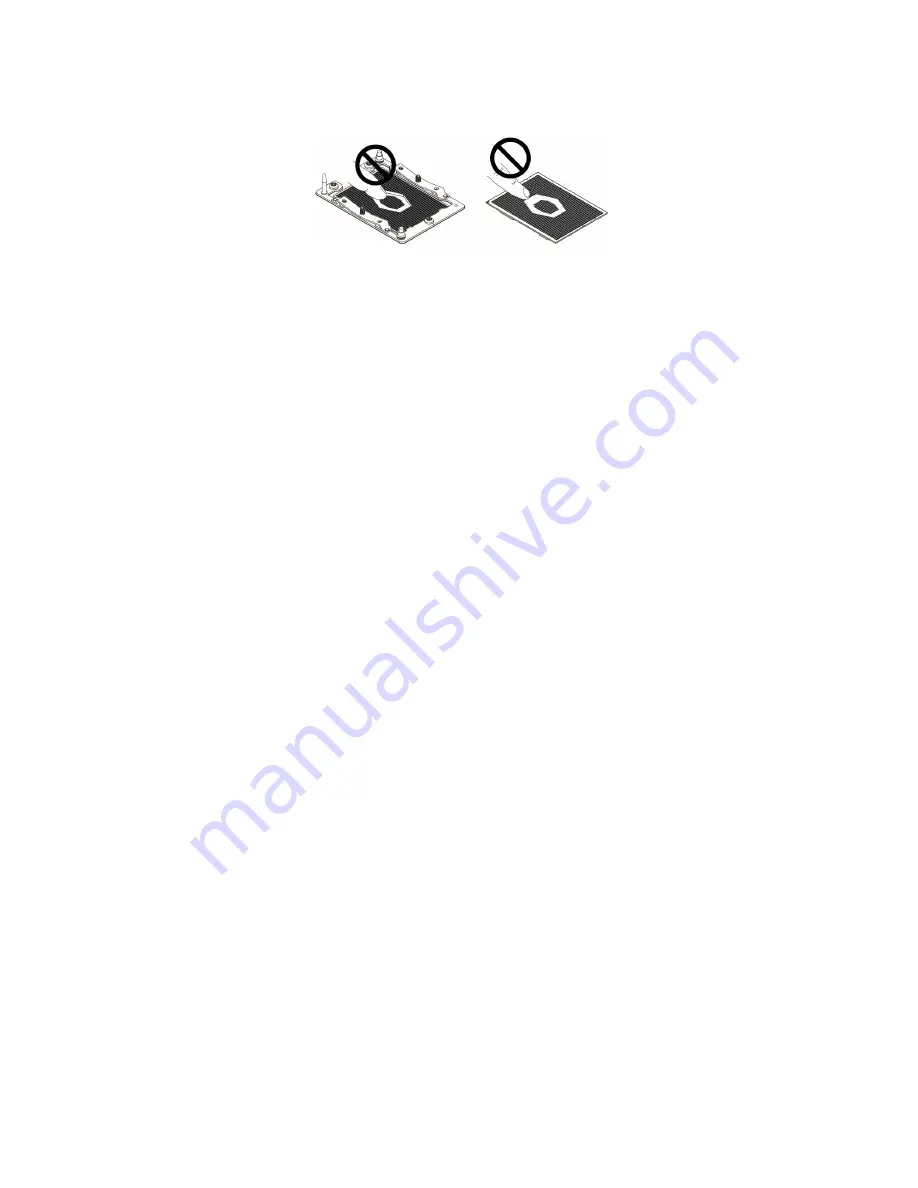
• Do not touch the pins on the microprocessor socket or the gold contacts on the microprocessor.
System board replacement procedure
1. Remove the computer cover. See “Computer cover” on page 62.
2. Remove the front bezel. See “Front bezel” on page 63.
3. Pivot the drive bay assembly upward. See “Pivot the drive bay assembly upward and downward” on
4. Remove the M.2 solid-state drive. See “M.2 solid-state drive” on page 75.
5. Remove all memory modules. See “Memory module” on page 80.
6. Remove all PCI Express cards. See “PCI Express card” on page 82.
7. Remove the Wi-Fi card. See “Wi-Fi card” on page 84.
8. Remove the front I/O bracket. See “Power button board and card reader” on page 87.
9. Remove the heat sink and fan assembly. See “Heat sink and fan assembly” on page 99.
10. Remove the microprocessor. See “Microprocessor” on page 102.
11. Record the cable routing and cable connections, and then disconnect all cables from the system board.
See “System board” on page 57.
12. Remove the nine screws that secure the system board, and then carefully lift the system board out of the
chassis.
Note:
Carefully handle the system board by its edges.
106
M75s-1 Hardware Maintenance Manual
Summary of Contents for 11A9000DGE
Page 1: ...M75s 1 Hardware Maintenance Manual ...
Page 6: ...iv M75s 1 Hardware Maintenance Manual ...
Page 13: ...Chapter 1 Important safety information 7 ...
Page 14: ... 18 kg 37 lb 32 kg 70 5 lb 55 kg 121 2 lb 1 2 8 M75s 1 Hardware Maintenance Manual ...
Page 17: ...Chapter 1 Important safety information 11 ...
Page 18: ...1 2 12 M75s 1 Hardware Maintenance Manual ...
Page 19: ...Chapter 1 Important safety information 13 ...
Page 25: ...Chapter 1 Important safety information 19 ...
Page 29: ...Chapter 1 Important safety information 23 ...
Page 38: ...32 M75s 1 Hardware Maintenance Manual ...
Page 46: ...40 M75s 1 Hardware Maintenance Manual ...
Page 117: ......
Page 118: ......


