Page 11
IMPORTANT
Use a thermocouple or thermistor electronic vacuum
gauge that is calibrated in microns. Use an instrument
that reads from 50 microns to at least 10,000 microns.
1 − Connect manifold gauge set to the service valve ports :
low pressure gauge to
vapor
line service valve
high pressure gauge to
liquid
line service valve
2 − Connect micron gauge.
3 − Connect the vacuum pump (with vacuum gauge) to the
center port of the manifold gauge set.
4 − Open both manifold valves and start the vacuum
pump.
5 − Evacuate the line set and indoor unit to an
absolute
pressure
of 23,000 microns (29.01 inches of mercu-
ry). During the early stages of evacuation, it is desirable
to close the manifold gauge valve at least once to deter-
mine if there is a rapid rise in
absolute pressure
. A
rapid rise in pressure indicates a relatively large leak. If
this occurs, repeat the leak testing procedure.
NOTE − The term
absolute pressure
means the total
actual pressure within a given volume or system,
above the absolute zero of pressure. Absolute pres-
sure in a vacuum is equal to atmospheric pressure mi-
nus vacuum pressure.
6 − When the absolute pressure reaches 23,000 microns
(29.01 inches of mercury), close the manifold gauge
valves, turn off the vacuum pump and disconnect the
manifold gauge center port hose from vacuum pump.
Attach the manifold center port hose to a nitrogen cylin-
der with pressure regulator set to 150 psig (1034 kPa)
and purge the hose. Open the manifold gauge valves to
break the vacuum in the line set and indoor unit. Close
the manifold gauge valves.
CAUTION
Danger of Equipment Damage.
Avoid deep vacuum operation. Do not use compres-
sors to evacuate a system.
Extremely low vacuums can cause internal arcing
and compressor failure.
Damage caused by deep vacuum operation will void
warranty.
7 − Shut off the nitrogen cylinder and remove the manifold
gauge hose from the cylinder. Open the manifold
gauge valves to release the nitrogen from the line set
and indoor unit.
8 − Reconnect the manifold gauge to the vacuum pump,
turn the pump on, and continue to evacuate the line set
and indoor unit until the absolute pressure does not rise
above 500 microns (29.9 inches of mercury) within a
20−minute period after shutting off the vacuum pump
and closing the manifold gauge valves.
9 − When the absolute pressure requirement above has
been met, disconnect the manifold hose from the vacu-
um pump and connect it to an upright cylinder of R−410A
refrigerant. Open the manifold gauge valves to break
the vacuum from 1 to 2 psig positive pressure in the line
set and indoor unit. Close manifold gauge valves and
shut off the R−410A cylinder and remove the manifold
gauge set.
C − Charging
Charge Using the Weigh-in Method
Outdoor
Temperature < 65ºF (18ºC)
If the system is void of refrigerant, or if the outdoor ambient
temperature is cool, first, locate and repair any leaks and
then weigh in the refrigerant charge into the unit.
1. Recover the refrigerant from the unit.
2. Conduct leak check; evacuate as previously outlined.
3. Weigh in the unit nameplate charge. If weighing facili-
ties are not available or if charging the unit during warm
weather, use one of the following procedures.
Charge Using the Subcooling Method
Outdoor
Temperature < 65ºF (18ºC)
When the outdoor ambient temperature is below 65°F
(18°C), use the subcooling method to charge the unit. If
necessary, restrict the air flow through the outdoor coil to
achieve pressures in the 325−375 psig (2240−2585 kPa)
range. These higher pressures are necessary for checking
the charge. Block equal sections of air intake panels and
move obstructions sideways until the liquid pressure is in
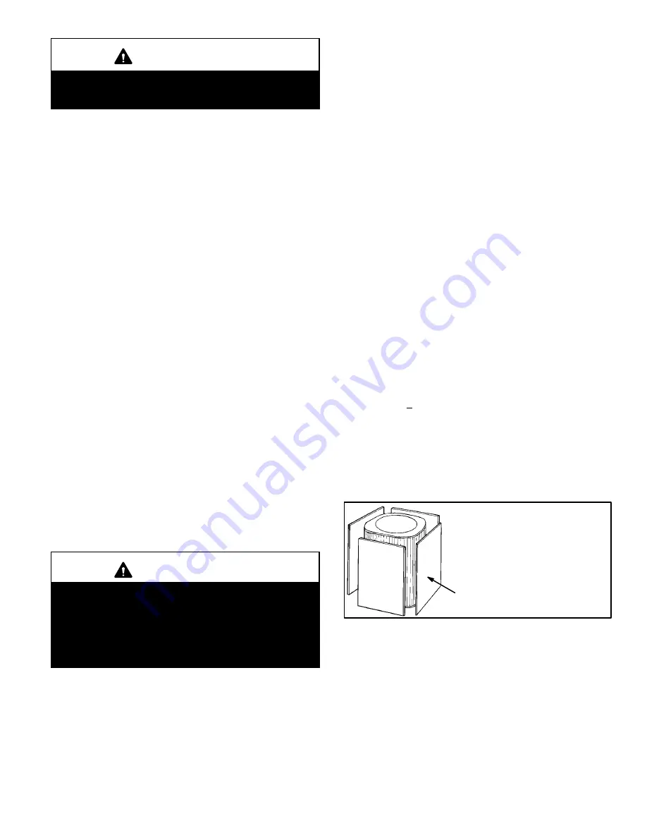
the 325−375 psig (2240−2585 kPa) range. See figure 15.
Blocking Outdoor Coil
BLOCK OUTDOOR COIL ONE
SIDE AT A TIME WITH
CARDBOARD OR PLASTIC
SHEET UNTIL PROPER TESTING
PRESSURES ARE REACHED.
CARDBOARD OR PLASTIC
SHEET
FIGURE 15
1. With the manifold gauge hose still on the liquid service
port and the unit operating stably, use a digital ther-
mometer to check the liquid line temperature and re-
cord in table 5.
2. At the same time, record the liquid line pressure reading.
3. Use a temperature/pressure chart for R−410A (table 4)
to determine the saturation temperature for the liquid
line pressure reading; record in table 5.


