37
Output Gain
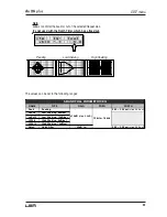
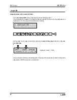
Output level control.
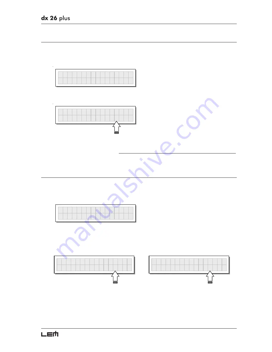
Allows to adjust the signal level of each individual output.
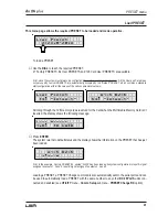
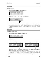
O u t p u t G a i n
Editing values are between
+6dB ÷ -30dB, with 0.5dB steps.
O P 1
G A I N
- 6 . 5 d B
N.B.: the level of each output is shown by the respective
OUTPUT LEVEL
LED ladder. To avoid distortion, don’t let
the red
CLIP
LED light up. As automatic protection, you can also enable the
LIMITER
(
EDIT
menu) on the outputs
that require it. In this case, remember that enabling the LIMITER changes the display mode on the relative LED ladder:
in fact, the level shown is no longer the “absolute” output level, but the level of the signal in relation to the LIMITER
threshold.
Output Pol.
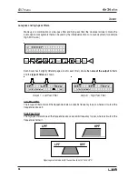
Controls the outputs’ polarity.
Allows to invert the phase of the signal of individual outputs.
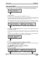
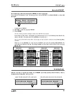
O u t p u t P o l .
Editing values are:
Normal
: leaves the phase unchanged
Reverse
: shifts the phase through 180°, inverting it.
O P 1
P O L A R I T Y
N o r m a l
O P 1
P O L A R I T Y
R e v e r s e
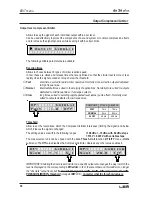
The effect of this control is summed with that of the
Φ
Φ
Φ
Φ
Φ
parameter of the
LPF
filter (
Xover
-
EDIT
menu),
which operates with 5° steps in a range of between 0° and 180°.
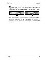
In this way it’s possible to set the phase of each individual output with 5° steps within a complete 360°
revolution, a very useful function when assembling arrays of speaker enclosures, in the control of the
interpolation between various enclosures or between sections of the same system.
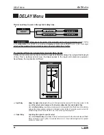
EDIT menu
Summary of Contents for DX 26 PLUS
Page 52: ...52 Configurations...
Page 53: ...53 Configurations...
Page 55: ...55 Connections...
Page 56: ...56 Connections...
Page 57: ...57 Connections...
Page 58: ...58 Connections...
Page 59: ...59 Communications PC one or more DX 26 PLUS connection Connections...
Page 64: ......

