background image

10

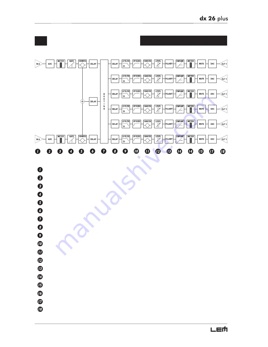
 Signal Processing 

Balanced inputs (IN A & IN B).
20-bit A/D converters.
LED ladders for monitoring input signals.
NOISE GATE on the inputs.
5-band parametric equalizers for A & B inputs.
3 delay lines (IN A, IN B & Sum A+B).
Routing System for connecting INPUTS and OUTPUTS.
Delay lines in 1-6 output.
Low-pass filters (LPF) with phase fine control - CROSSOVER.
High-pass filters (HPF) - CROSSOVER.
5-band parametric equalizers for the outputs.
Output level controls.
Polarity inverter.
Output level COMPRESSOR/LIMITERS.
LED ladders showing output levels and limiter action.
Output MUTING controls.
20-bit D/A converters.
XLR-M balanced outputs.

Signal Processing

Summary of Contents for DX 26 PLUS

Page 1: ...the System 12 Adjusting the input signal 13 First Setup 14 Display information in default conditions 15 System configuration 15 Number of PRESETS 16 Type of PRESET 16 Name of the PRESET 16 PRESET Modi...

Page 2: ...quency 32 Bandwidth 32 Gain 33 Xover 34 Low Pass Filter 34 High Pass Filter 34 Type of filter 35 Crossover frequency 35 Phase 35 Output EQ 36 Output Gain 37 Output Pol 37 Output Compressor Limiter 38...

Page 3: ...46 Lock submenu 47 How to enable protection 47 Protection mode 47 Password 47 How to disable the protection 48 Memory Card submenu 49 How to format the Card 49 Comm Setup submenu 50 PRESET Change RX...

Page 4: ...Don t force knobs or switches these are designed and manufactured to respond to light pressure and could be damaged if used with excessive force Take care of your connector cables a very frequent cau...

Page 5: ...Q CROSSOVER HP and LP filters which can be selected from the BESSEL BUTTERWORTH and LINKWITZ RILEY types with slopes up to 48dB phase control with 5 steps through a full 360 digital COMPRESSOR LIMITER...

Page 6: ...Y Rear lit 2x16 display Allows to view the pages of the various menus and the relative parameters PREV NEXT Menu page navigation keys Each menu is made up of several pages which can in turn contain ot...

Page 7: ...P OUTPUT LEVEL 1 2 3 4 5 6 LED ladders showing the level of the respective outputs N B the output level is adjusted using the OUTPUT GAIN parameter EDIT menu IMPORTANT Enabling the LIMITER on any outp...

Page 8: ...has the same processing as that connected to analog input OUTPUTS 1 2 3 4 5 6 Audio outputs Balanced XLR M connectors The D A conversion is made with high quality low noise 20 bit converters RS232 RS2...

Page 9: ...d ports and for daisy chaining several DX 26 PLUS POWER Unit s ON OFF switch Before switching on or off make certain that the sound system s amplifiers are off to avoid signal peaks which are annoying...

Page 10: ...ing System for connecting INPUTS and OUTPUTS Delay lines in 1 6 output Low pass filters LPF with phase fine control CROSSOVER High pass filters HPF CROSSOVER 5 band parametric equalizers for the outpu...

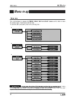
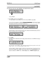
Page 11: ...and functions The navigation i e access to the system s menus and changes of the various parameters follow logical criteria which can be summed up as follows The menu is selected using the MODE key Th...

Page 12: ...cludes the last PRESET loaded all the temporary changes if any made to it and the settings of the various options of the system The system then enters default status showing the main operating informa...

Page 13: ...t level setting for your mixer or other unit connected to the input of the DX 26 PLUS Then adjust the DX 26 PLUS input gain if necessary Press the MODE key until the EDIT menu LED lights up Use the PR...

Page 14: ...ocumentation and technical specifications of your power amplifiers loudspeaker enclosures monitors etc This will enable you to work faster and safely Disable the MUTE function on the outputs you inten...

Page 15: ...figuration A 1 3 B 2 4 S 5 6 2 U 2 x 2 W 2 M A X System configuration The bold letters indicate the inputs A Input A B Input B S SUM sum of inputs A and B Numbers 1 2 3 4 5 and 6 indicate the respecti...

Page 16: ...eating User PRESETS and Card PRESETS from scratch U User PRESETS can be programmed by users C Card PRESETS can be programmed by users and stored on a Multimedia Memory Card Name of the PRESET A 1 3 B...

Page 17: ...ndication disappears as soon as stored values are accessed If the PRESET isn t saved temporary changes are lost as soon as a new PRESET is loaded including this same PRESET N B temporary changes are k...

Page 18: ...ters parameters menu EDIT Input Gain Input EQ Noise Gate Xover Output EQ Output Gain Output Pol parameters parameters parameters parameters parameters parameters parameters Output Cmp Limit parameters...

Page 19: ...etup Preset Change RX Ganging Input Ganging Output Ganging Delay Unit Units Lim Thresh Unit Temperature Unit Input Select Misc Setup Output Meters Temperature Wake Up LCD Contrast Lock Lock Memory Car...

Page 20: ...uts For example it allows to equalize simultaneously and with identical values the two outputs which feed the mid sections of a stereo sound system The Units option UTILITY menu allows to edit the val...

Page 21: ...y OFF 2 INA Delay SUM Delay ON 2 INA Delay SUM Delay OFF 3 INA Delay INB Delay SUM Delay ON 3 INA Delay INB Delay SUM Delay OFF 2 INA Delay SUM Delay ON 2 INA Delay SUM Delay OFF 3 INA Delay INB Delay...

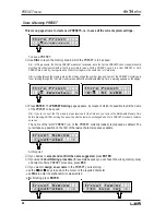
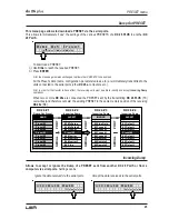
Page 22: ...Factory PRESETS contain some specific set tings for certain types of enclosures and all the system s usable configurations For this reason they re the ideal starting point for creating custom PRESETS...

Page 23: ...f a u l t Scrolling through the 128 memory areas reserved for the Card when the Multimedia Memory Card isn t inserted the display shows the following message L o a d Pr e s e t 1 2 8 C N O C A R D Pre...

Page 24: ...he PRESET Naming page appears by means of which it s possible to edit the name of the PRESET to be saved N B if you re in one of the 128 memory areas reserved for the Card and you remove the Multimedi...

Page 25: ...itting DX 26 PLUS TX overwrites and therefore cancels the existing PRESET in the same memory position of the receiving DX 26s RX DX 26 1 DX 26 2 DX 26 3 DX 26 4 Dump Out Preset Incoming Dump Incoming...

Page 26: ...outputs are equivalent Nevertheless their application is different OUTPUT DELAY INPUT DELAY DELAY Input Delay delays the signal of an input or the sum of the inputs before sending it to the routing sy...

Page 27: ...set in the following ranges I N A D E L A Y 7 7 m s unit step m 0 0 900 0 0 5 mm 0 900000 7 ms 0 2621 1 us 0 2621438 21 range INPUT DELAY The measurement unit can be chosen with the function Delay Un...

Page 28: ...9 2 u s unit step m 0 0 100 0 0 5 mm 0 100000 7 ms 0 291 1 us 0 291271 21 OUTPUT DELAY range The measurement unit can be chosen with the function Delay Unit UTILITY menu Units submenu 18ms 6 5m OP1 DE...

Page 29: ...e used in the most suitable form of editing Input Gain Input gain control I n p u t G a i n Allows to adjust the amplification of the signal fed in through Inputs A and B Editing values are in the ran...

Page 30: ...et the Noise Gate attack and release times ATTACK AT is the time needed by the filter to bring back the signal to its normal level when it goes above the threshold RELEASE RL is the time needed by the...

Page 31: ...the input and the input SUM This component s characteristic quality and programmability identical to the output Equalizer enable it to be used so effectively and flexibly as to make the use of graphic...

Page 32: ...quency of the Peaking curve and Notch filter or the cutoff frequency of Shelving curves I N A E Q 1 P e a k 2 k 0 0 1 0 5 0 Peaking Low Shelving High Shelving Notch 20dB 15dB 10dB 5dB 0dB 5dB 10dB 15d...

Page 33: ...0dB 5dB 10 dB 15 dB 20 dB 10Hz 100Hz 1 000Hz 10 000Hz 100 000Hz 20dB 15dB 10dB 5dB 0dB 5dB 10 dB 15 dB 20 dB 10Hz 100Hz 1 000Hz 10 000Hz 100 000Hz The values can be set in the following ranges NAME T...

Page 34: ...the output it affects and the type of filter are shown O P 1 L P F T h r u 1 k 0 0 H z O O P 1 H P F T h r u 1 k 0 0 H z Output 1 Low Pass Filter Output 1 High Pass Filter Low Pass Filter The low pass...

Page 35: ...r u 1 k 4 6 H z O Phase Allows fine control in 5 steps of the signal s phase The effect of this control is summed with that of the Output Polarity function 0 180 In this way it s possible to adjust th...

Page 36: ...and enable this unit to be used extremely effectively and flexibly O u t p u t E Q Each equalizer has 5 pages one per filter indicating the name of the output it effects and the num ber of the filter...

Page 37: ...l of the signal in relation to the LIMITER threshold Output Pol Controls the outputs polarity Allows to invert the phase of the signal of individual outputs O u t p u t P o l Editing values are Normal...

Page 38: ...rapid repeated level jumps pump effect Normally most suited to outputs dedicated to low frequencies O P 1 C o m p L i m F a s t 3 0 O f f COMP LIMIT ATTACK RELEASE FAST 1 ms 10 ms NORMAL 8 ms 80 ms SL...

Page 39: ...3 0 O f f O P 1 C o m p L i m F a s t L i m O f f The Lim value corresponds to the maximum compression ratio all the signal exceeding the threshold is cut and in this condition the processors acts as...

Page 40: ...control of the Multimedia Memory CARD or protection against accidental or unauthorized changes menu UTILITY Comm Setup Preset Change RX Ganging Input Ganging Output Ganging Delay Unit Units Lim Thres...

Page 41: ...its characteristics the Ganging function affects the way in which the relative parameters audio are edited or represented As soon as Inputs and or Outputs are ganged the various menu pages only show t...

Page 42: ...DIAL changes the status of the old value So if the value which has to be allocated to the elements in Ganging is the same as the old value it s necessary to use the DIAL temporarily change the value e...

Page 43: ...ment units for Output Delay D e l a y U n i t I n m s O u t s D e l a y U n i t I n m O u t m m Lim Thresh Unit Allows to set the measurement units for the threshold of the Limiter EDIT menu Output Li...

Page 44: ...s of system options M i s c S e t u p Input Select Allows to choose which DX 26 PLUS inputs to use The options include Digital Inputs Analog Inputs I n p u t S e l e c t A n a l o g I n p u t S e l e...

Page 45: ...tomatically compensate for the differentials due to the difference speed of sound transmission according to the air temperature This allows to set the delays during the sound check and only have to re...

Page 46: ...d on the system restores the last when switched on the system automatically MUTE configuration before switching off sets all the outputs in MUTE W a k e Up N o r m a l W a k e Up M u t e LCD Contrast...

Page 47: ...functions are blocked and access to the PRESET menu disabled L O C K T o t a l P a s s w o r d N I C K L O C K P a r t i a l P a s s w o r d N I C K Then use the and keys to access the area in which t...

Page 48: ...re changes that have not yet been stored You can however switch the system on and off without any problems as the current settings are kept in the buffer memory Nevertheless if this is your work setup...

Page 49: ...communicates that it has completed This operation only requires a few seconds The Card is ready to be used F o r m a t C a r d F o r m a t t i n g F o r m a t C a r d F o r m a t D o n e N B in the ev...

Page 50: ...ntaining a number of PRESETS to load the receiving units if they are able to accept the command each loads into its own memory the PRESET with the corresponding number This means that in a chain of DX...

Page 51: ...51 Configurations The following diagrams show the DX 26 s various system configurations as if to say the various input and output hardware combinations Configurations...

Page 52: ...52 Configurations...

Page 53: ...53 Configurations...

Page 54: ...e schemes of the recommended cables and some connection examples referred to various system configurations Inputs A B Digital IN RS485 IN BALANCED XLR M Inputs A B BALANCED JACK Outputs 1 6 RS485 OUT...

Page 55: ...55 Connections...

Page 56: ...56 Connections...

Page 57: ...57 Connections...

Page 58: ...58 Connections...

Page 59: ...59 Communications PC one or more DX 26 PLUS connection Connections...

Page 60: ...60 Communications two DX 26 PLUS short distance connection Communications two or more DX 26 PLUS long distance connection Connections...

Page 61: ...C3 50W 8ohm PFC3 300W 8ohm 15 K3 KL A135 B246 1 x K3 1 x KL for each side PFC3 50W 8ohm PFC3 300W 8ohm PFC5 600W 8ohm 16 TM18 PR A135 B246 1 x TM18 3 MH 1 x TM18 3 L for each side PFC3 90W 8ohm PFC3 2...

Page 62: ...291 ms outputs EQ filters Up to 40 maximum depending on the crossover slope EQ Type Peak 6dB Lo Shelf 12dB Lo Shelf 6dB Hi Shelf 12dB Lo Shelf Notch EQ Gain 15dB variable in 0 5dB steps EQ Bandwidth 0...

Page 63: ...ventuali inesatezze Tutti i diritti sono riservati e in questo documento non pu essere copiato fotocopiato riprodotto per intero o in parte senza previo consenso scritto della GENERALMUSIC S p A GENER...

Page 64: ......
Reviews: