8. Position the burner tray into the box in order to determine the length of 8mm
gas supply needed and cut to length.
9. Before making the final connection, thoroughly purge the supply pipe
to clear any foreign matter, i.e. masonry dust etc, as this could lead to
blockages in the control valve and/or pilot assemblies.
10. Fix the burner in place using the four screws and make the gas
connection. Carry out a gas soundness test.
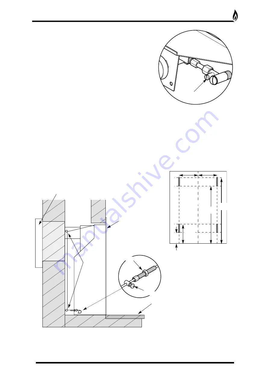
11. Unscrew the pressure test point sealing screw (Fig. 10) and fit a
manometer. Consult the user instructions (page 14). Ignite the
appliance and turn to the high position.
12. Take a pressure reading and consult the technical data (page 11) to
establish the correct working pressure.
13. Once the pressure has been checked and verified, turn off the appliance. Consult the ceramic component set
up diagrams (page 16 - 21) and fit the ceramics as per the instructions.
14. Carry out a Spillage Test.
ALTERNATIVE FIXING METHOD
Where the drilling of the back panel is not practical, an alternative fixing method may be employed using the
cable fixing kit provided. Drill four holes in the rear of the fireplace opening (Fig. 11). Securely fix the four eye
bolts provided using suitable rawl plugs. Feed one cable through each of the top holes in the rear of the
fire box.
Fix the radiant box into the opening, securing into position using the cable fixing kit (Fig. 12). Do not cut off the
loose ends as the full length is required should the radiant box need refitting at any time. Coil up and securely
store underneath the burner tray.
INSTALLATION PROCEDURE
CONTINUED
10
Centre Line
Drill Holes for 4 eye bolts
on 112mm centre lines
between max and min height.
65mm
min
115mm
max
500mm
min
550mm
max
112mm
112mm
Fig. 11
Radiant box
Outer fan cover
Hearth
Eye Bolts
Tension Nut
Cable Clamping Screw
Fig. 12
Fig. 10
Pressure Test Point


