3. Installation
164201241-001 Rev. C0
15
3.4
Wall Mounting and Electrical Connection (
Models PSF-W00-D**, PSF-W00-D09, and
PSF-W00-D15)
1.
Install an agency-approved service disconnect switch with overcurrent protection,
between the AC power source and the cabinet mounting point. Wire to power line
in accordance with local codes.
2.
Power to the MiniMax is supplied with a round service cable such as UL type SJT-
16/14-3 (3 x 1mm²) conductor (max. dia. 11.5mm/0.47") from the service
disconnects to the inside of the unit. Allow enough length for an adequate service
loop.
3.
If mounting to sheet rock or paneling, find the wall studs for secure mounting.
4.
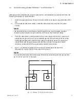
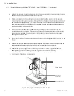
Mount to wall with appropriate hardware, such as (6) M5 x 25mm wood screws.
5.
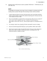
Route service (mains) cable in through the bottom of the unit via the black nylon
fitting. After cable is inserted to the proper position, twist fitting knob in the
clockwise direction to tighten on cable.
Fig. 3-6 Service Cable Routing
Service (Mains) Cable
Coax Connector
Nylon Cord Fitting
NOTE
The MiniMax non-standby power supply must be installed in accordance with local
building codes to prevent damage to the mounting structure and the unit itself.


