3. Installation
164201241-001 Rev. C0
13
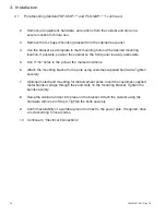
Verify the utility disconnect is off and that no conductors are
energized before proceeding.
1.
Open the housing cover and place a screwdriver blade in the small notch at the top
of the housing to hold the cover in place.
2.
Install a liquid tight conduit to the fitting on the cabinet bottom and pull the AC
primary wiring in to the cabinet housing.
3.
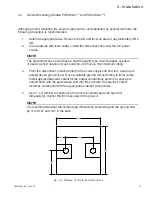
Remove the necessary receptacle knockout and install the receptacle provided as
shown. Connect the AC high input to the receptacle terminal labeled MAIN, the AC
neutral input to the receptacle labeled N, and the utility protective ground (green/
yellow) to the green receptacle terminal. Tighten the screw to a torque of 20 lb-in.
4.
Position all wiring neatly in the receptacle box and install the receptacle and cover.
5.
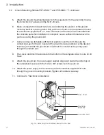
Using the output wire harness (green and yellow wires with power lock connectors,
a seizure clamp, and O-ring), and cable adapter from the parts kit, install the cable
adapter and ground wire. Insert the cable adapter from the outside of the cabinet
into the paint-masked hole, along with the supplied cable feed guard bracket for
ground mount installation. Use the locknut to secure the adapter and the large O-
ring to the cabinet. Tighten securely.
6. Prepare the incoming coaxial cable used for the distribution of power (including
external fittings not supplied by Alpha).
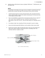
7. Loosen the brass seizure screw output fitting to accommodate the center pin
(“stinger”) of the cable connector.
3.3
Electrical Connections for Pole and Ground Mounts
Fig. 3-5 Receptacle Connections
WARNING
The center conductor may also be trimmed to allow for a flush fit. The length of the
center conductor must be 1.25” from the end to the center of the O-Ring.
NOTE


