Hardware
installation manual of the multi-axis drive MX4660
Leadshine Technology Co., Ltd
Leadshine America, Inc.
Page 21/28
3/F, Block 2, Nanyou Tianan Industrial Park, Shenzhen, China
25 Mauchly, Suite 318, Irvine, CA 92618, USA
Tel: 86-755-26409254
Fax: 86-755-26402718
Tel: 1-949-608-7270
Fax: 1-949-608-7298
Web:
www.leadshine.com
Email:
Web:
www.leadshine.com
Email:
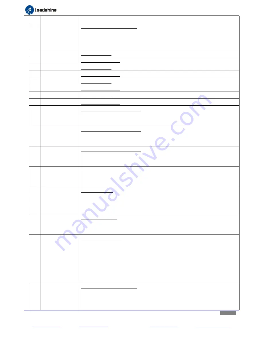
Pin
Name
Description
1
INPUT 2
General purpose digital input. It is connected to “Output 2” of the digital output
connector (CN8 on Figure3). Used to forward an input signal sent from the
connected motion controller to the device connected at “Output 2”.Its maximum
frequency up to 200 kHz.
2
X-AXIS STEP
Input step signal for the X-axis stepper drive board.
3
X-AXIS DIRECTION
Input direction signal for the X-axis stepper drive board.
4
Y-AXIS STEP
Input step signal for the Y-axis stepper drive board.
5
Y-AXIS DIRECTION
Input direction signal for the Y-axis stepper drive board.
6
Z-AXIS STEP
Input step signal for the Z-axis stepper drive board.
7
Z-AXIS DIRECTION
Input direction signal for the Z-axis stepper drive board.
8
A-AXIS STEP
Input step signal for the A-axis stepper drive board.
9
A-AXIS DIRECTION Input direction signal for theA-axis stepper drive board.
10
OUTPUT 1
General purpose digital output. It is connected to “Input 1” of the digital input
connector (CN7 on Figure3). Used to forward an output signal from the device
connected at “Input 1”, to the motion controller.
11
OUTPUT2
General purpose digital output. It is connected to “Input 2” of the digital input
connector (CN7 on Figure3). Used to forward an output signal from the device
connected at “Input 3”, to the motion controller.
12
OUTPUT3
General purpose digital output. It is connected to “Input 3” of the digital input
connector (CN7 on Figure3). Used to forward an output signal sent from the device
connected at “Input 3”, to the motion controller.
13
OUTPUT4
General purpose digital output. It is connected to “Input 4” of the digital input
connector (CN7 on Figure3). Used to forward an output signal sent from the device
connected at “Input 4”, to the motion controller.
14
PWM
PWM pulse input. Used to get the PWM signal from the controller which will be then
transformed into ananalog signal to an external device connected at “0-10V out” pin
of the analog output connector (CN8 on Figure 3), such as a VFD for spindle speed
control.
15
FAULT
Fault signal output back to a motion controller. It will beactivated (voltage high)
when one of the following events occurs: (1) a signal from ESTOP; (2) any of the 4
built stepper drive modules fails, or is activated for protection.
16
CHARGE PUMP
General digital input. A watchdog timer to disable/enable the MX4660. When
“Charge Pump” (Figure5) is set to “OFF” position (Charge pump feature NOT turned
off), the MX4660 will be only enabled with 10 KHz signal receiving at this PIN.
Otherwise (no such signal received), the MX4660 will be disabled, and you need to
set the switch to “ON” position if the user would like to operate/enalbe the drive
without such singal received. For example, in Mach3 controlled CNC applications,
MX4660’s enabling/disabling will depend on the receiving of “Charge Pump” signal
from Mach 3. When the MX4660 is enabled, Charge Pump LED will be on.
17
INPUT 1
General purpose digital input. It is connected to “Output 1” of the digital output
connector (CN8 on Figure3). Used to forward an input signal sent from the
connected motion controller to the device connected at “Output1”.Its maximum
frequency up to 200 kHz.


