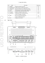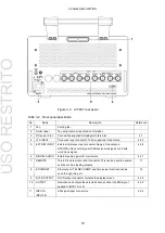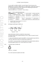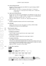
4. BEFORE YOU BEGIN MEASURING
23
5
Dolby indication (option; to be supported in the future)
Displays DOLBY-E when Module is set to Dolby-E and DOLBY-D when Module is set to
Dolby-Digital on the DOLBY tab in the system settings. The input group is also displayed.
[Reference] DOLBY tab → See section 5.5, “Configuring the Dolby Settings (Option).”
6
Channel
Displays channels that are receiving input in white (ocher during Dolby measurement)
and those that are not in gray.
7
MEAS, CALC, RMT, TC, CM
Displays loudness measurement information.
[Reference] See 5.7,
“Configuring Loudness Settings.”
MEAS: Appears when loudness measurement is in progress
CALC: Appears for a given period of time after loudness measurement is stopped
RMT:
Appears when loudness measurement is performed through the remote
connector
TC:
Appears when loudness measurement is performed using time codes
CM:
Appears when loudness measurement is performed using CM submission data
reference triggers.
8
LOG
Appears when events are being logged. To turn event logging on and off, use LOG in the
status menu.
[Reference] LOG → Section 10.3.2, “Configuring the Event Log”
9
AUDERR, SDIERR
Appears when an error occurs in one of the detection items that have been enabled on
the AUDIO ERROR tab or SDI ERROR tab (LV 5838 only) in the system settings.
Errors that are currently occurring and errors that have occurred in the past are
distinguished as follows:
[Reference] AUDIO ERROR tab → See 5.8, “Configuring Audio Error Detection Settings.”
SDI ERROR tab
→ See section 5.10, “Configuring SDI Error Detection Settings (LV 5838
only).”
10
Headphone
Displays the volume set with the VOLUME knob and the output channel set with
PHONES L and PHONES R in the assign menu.
[Reference] See section 4.2.2,
“Headphone Output.”
11
Key lock
Appears when the key lock is enabled. You can turn the key lock on and off by holding
down the SYSTEM key.
[Reference] See section 4.4.8,
“Setting the Key Lock.”
12
USB
Appears when a USB memory device is connected to the USB port. This indicator is
normally green, but it changes to red when the USB memory device is being accessed.
Do not turn the power off or remove the USB memory device when the indicator is red.
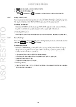
USO
RESTRITO


