
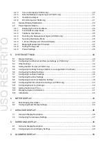
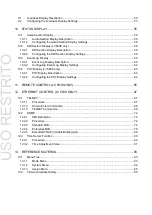


8
2. SPECIFICATIONS
2.3.2
Embedded Audio Playback Method (LV 5838 only)
Compliant Standards
3G-SDI, HD-SDI
SMPTE ST 299
SD-SDI
SMPTE ST 272
Format
LPCM, Dolby E (option), Dolby Digital (option), and
Dolby Digital Plus (option)
Quantization
24 bits
Clock Generation
Generated from the video clock
Synchronization
All audio signals must be synchronized to the video
clock.
*
The Dolby option will be supported in the future.
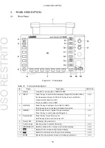
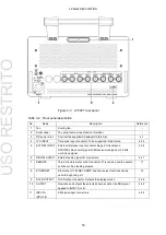
2.3.3
I/O Connectors
SDI Signal I/O Connectors (LV 5838 only)
Input Connector
2 BNC connectors
Input Impedance
75
Ω
Input Return Loss
5 M to 1.485 GHz
15 dB or more
1.485 to 2.97 GHz
10 dB or more
Maximum Input Voltage
±2 V (DC + peak AC)
SDI Signal Output Connector (LV 5838 only)
Output Connector
1 BNC connector
Output Signal
Transmits a serial reclocked signal of the signal received
through the SDI signal input connector
Output Impedance
75
Ω
Output Return Loss
5 M to 1.485 GHz
15 dB or more
1.485 G to 2.97 GHz
10 dB or more
Audio Signal Input/Output Connectors
I/O Connectors
8 BNC connectors, 16 channels
I/O Impedance
75
Ω
Supported Formats
LPCM, Dolby E (option), Dolby Digital (option), and
Dolby Digital Plus (option)
Sampling Frequency
32 k to 192 kHz
Quantization
24 bits
Maximum Input Voltage
±5 V (DC + peak AC)
Output Voltage
1.0 Vp-p ± 10 % (into 75
Ω)
Headphone Jack
Output Connector
One 3.5 mm mini jack
Output Signal
Two channels out of all the input audio signals
Volume Adjustment
VOLUME knob
Output Voltage
100 mW maximum (into 8
Ω load resistance)
USO
RESTRITO


