26
Fig. 2-16 3-phase in and 1 phase out, common input
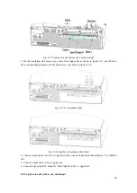
3. Fix the insulating film (accessory) to the No.6 copper bar as shown in figure 2-17, and fixed in
the corresponding position with the plastic rivet, as shown in figure 2-18.
Fig. 2-17 Fix insulation film
Fig. 2-18 Graphic of insulation film fixed
4. Connect input phase A to No.6 copper bar, then connect input phase B and phase C to mB and
mC.
5. Connect output cable to No.4 copper bar.
6. Connect bypass input N, output N, Main input N to No.7 copper bar.
2.8.4 3-phase in and 1 phase out, dual input


