21
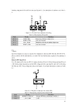
Interfaces diagram for J2 and J3 are shown in Figure2-11, the description of interface is in Table 2-
6.
J2
J3
T
E
M
P
_
B
A
T
T
E
M
P
_
E
N
V
Figure 2-11
J2 and J3 for temperature detecting
Table 2-6
Description of J2 and J3
Port
Name
Function
J2-1
TEMP_BAT
Detection of battery temperature
J2-2
TEMP_COM
common terminal
J3-1
ENV_TEMP
Detection of environmental temperature
J3-2
TEMP_COM
common terminal
Note
Specified temperature sensor is required for temperature detection (R25=5Kohm, B25/50=3275),
please confirm with the manufacturer, or contact the local maintenance engineers when placing an
order.
Remote EPO Input Port
J4 is the input port for remote EPO. It requires shorting NC and +24Vand disconnecting NO and
+24V during normal operation, and the EPO is triggered when opening NC and +24V or shorting
the NO and +24V. The port diagram is shown in Figure2-12 and port description is shown in Table
2-7.
E
P
O
_
N
C
+
2
4
V
+24V
Figure 2-12
Diagram of input port for remote EPO
Table 2-7
Description of input port for remote EPO
Port
Name
Function
J4-1
REMOTE_EPO_NC
Trigger EPO when disconnect with J4-2
J4-2
+24V_DRY
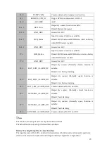
+24V


