PowerReclineXRw
™
Motion Sofa
Assembly Instructions
PowerReclineXRw
™
Motion Sofa
Assembly Instructions
17
16
F
IGURE
7
F
IGURE
8
F
IGURE
11
Back
Bracket
45 Degrees
from
Vertical
Locking
Lever
(Assembly Instructions Continued)
Motor Connectors
Base Rail
Lock
Washer
Upper Jam Nut
Lower Jam Nut
Adjustable Glide
– To reduce the risk of serious injury:
• Provide a clear path for operation of the back and legrest. Place tables and area rugs
at a distance to allow the legrest to fully extend without rubbing or interference.
F
IGURE
9
F
IGURE
10
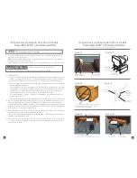
5. Adjust the glides to ensure a height that provides a clear path for operation of the legrest. Each glide is
attached to the base rail by one jam nut and one lock washer on top of the base rail, and one jam nut
on the bottom of the base rail.
•
To extend the glide, loosen the upper jam nut by rotating clockwise. Turn the lower jam nut
clockwise to the desired height.
•
Tighten the upper jam nut by rotating counterclockwise.
•
Repeat steps one and two for each adjustable glide on the unit, if needed.
•
Repeat this procedure, as necessary, to adjust the front height of the unit and level it.
6. Locate the motor connector, one behind each reclining seat (F
IGURE
7). Connect the Y-cable to the
motor connectors and to the power supply.
•
Align one motor connector to a long lead Y-cable connector, push the connectors together until
seated and close the locking cover to secure the connection (F
IGURE
8). Repeat this for the other
motor connector and Y-cable long lead. Then align the short lead of the Y-cable to the power supply
connector, push the connectors together until seated and close the locking cover to secure the
connection (F
IGURE
9).
7. Connect the 120 volt power cord to the power supply (F
IGURE
10). Do not plug in until instructed in
the
Operating Instructions
.
8. Proceed to the
Battery Backup Assembly Instructions
.
To Remove a Back:
1. Unplug the 120 volt power cord from the electrical outlet and disconnect the power supply from
the Y-cable.
2. Taking care not to damage the cover, insert a screwdriver between the arm and back and engage
the locking lever on the back bracket (F
IGURE
11).
3. Push up on the locking lever until the lever is at 45 to 30 degrees from vertical (F
IGURE
11).
4. Repeat steps 2 and 3 for the other side of the back, inserting the screwdriver between
the rear post and back.
5. The back is free to remove at this point. Lift up on the back to remove.
WARNING
Y-Cable Long Leads
Make this
connection
Power Supply
Y-Cable Short Lead
Make these
connections
Make this
connection
Power Supply
120 Volt Power Cord


