background image


              - 69 -     

Mercury II User Manual


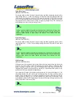
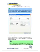
allows you to increase the width of the ridge base, hence creating more stable 
“contact sections” and longer lasting stamp. The pitch value setting allows you to 
adjust the base width of the ridge.    Broad pitch gives the maximum amount of 
support for each ridge.    Experiment with different pitch value settings in order to 
produce the stamp that is best suited for your application.   


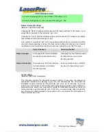
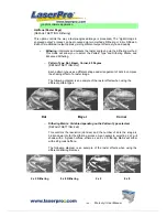
Adjustment Bar / Power Level (Stamp Page)


Another important aspect of creating a stamp is setting the slope level of the shoulder. The 
shoulder is the section from the “contact section” of the stamp to its base. This function 
allows you to adjust the slope for the shoulder sections of your stamp. By sliding the sliders 
or directly input of power levels, you will be able to change the slope of the shoulder. 


NOTE 

The visual representations of the Pitch and Shoulder Levels in the Mercury II driver 
are an exaggerated representation to allow for easy visual guidance and precise 
input. Remember we are working with distances less than 1 mm here. 


Summary of Contents for Mercury II

Page 1: ......

Page 2: ... 17 Chapter III HARDWARE INSTALLATION 18 3 1 Cabling Connection 18 3 2 Parallel Transmission 18 3 3 USB Transmission 18 3 4 Exhaust Ventilation 19 Chapter IV SOFTWARE INSTALLATION 20 4 1 Install LaserPro Mercury II driver to PC Please follow the procedure below 20 Chapter V Operating the LaserPro Mercury II 21 5 1 Using the Hardware 21 5 1 1 Adjusting the LCD Display Screen s Contrast Setting 21 5...

Page 3: ... Driver Paper Page 62 5 2 3 5 Mercury II Print Driver Language Page 64 5 2 3 6 Mercury II Print Driver Raster Page 65 5 2 3 7 Mercury II Print Driver Stamp Page 68 Chapter VI BASIC MAINTENANCE 70 6 1 Clean the mirror Please refer to the figure as below 70 6 2 Clean the focus lens 72 Chapter VII TROUBLE SHOOTING 73 7 1 Quality Problems 73 7 2 Non operational Problems 73 Appendix A 3D Function 74 Ti...

Page 4: ... at the focal position automatically 8 The following is an example by using CorelDRAW V 11 Please ready the engraving graphic in CorelDraw and follow the instruction below to start work 1 Layout 2 Page Setup 3 Set from Printer choose Portrait 4 OK 5 Edit desired file picture etc 6 File 7 Print 8 Properties 9 Options choose desired Mode refer to Fig 11 then set up proper resolution power and speed ...

Page 5: ...such as mirrors enameled brass and anodized aluminum may reflect a portion of the invisible laser radiation This may cause sever eye damage if appropriate safety goggles are not worn NOTE Each LaserPro laser machine is equipped with a safety goggle if you need another one please contact LaserPro for it or try to get one that meets the following specification 190 398 nm OD5 10 600 nm OD5 Visible li...

Page 6: ...y with materials mentioned above 1 5 The Safety Interlock System The LaserPro MERCURY is complete with a safety interlock system that automatically shuts off the power supply to the laser whenever the top or front door is opened There are magnets on the top and front door which activate this safety mechanism Do not attempt to remove or modify these magnets or any other component of the safety inte...

Page 7: ...ld be done by your dealer 3 What is the main purpose of air assist system The air assist system can provide a much better engraving cutting effect as it will blow away vaporized particles and prevent fire due to overheating 4 What does cutting table do The cutting table also known as honeycomb table is especially useful for vector cutting application The space between materials and working table g...

Page 8: ...magnetic devices to short the connector of the magnetic switches on both side of the front door while opening for engraving extremely long work piece When doing so make sure that you wear safety go ggles to operate the machine ...

Page 9: ...el Laser Source Switches Ports Top Door Front Door Air inlet connect to air compressor Press the ring to pull out the air tube Air Flow Fixer Turn clockwise to decrease the air flow and counterclockwise to increase the air flow Please avoid turn off ...

Page 10: ...o maintain 1 mirror Please refer to the right layout Laser source inside Rear Door Unscrew and remove the panel Step 1 Unscrew and remove the dust prevention box Step 2 Unscrew and pull out 1 mirror carefully without touching the surface of the mirror Step 3 ...

Page 11: ... Auto focus Gauge Manual Focus Gauge Holder Mirror 4 and Focus Lens inside Dust Prevention Box Mirror 2 inside Mirror 3 Holder X axis Bearing X axis Belt Bearing Track Y axis Belt Magnetic Sensor for Dual Head Port for Rotary Attachment Release the Screw to Pull Out the Mirror ...

Page 12: ...5 Option Purple Blue same as 2 0 2 0 Standard Blue Blue 2 5 Option Gold Gold 4 0 Option Red Red Manual Focus Gauge Holder Insert to the hole of the holder for manual focusing Mirror Lens 2 0 2 5 or Slot position for Lens 1 5 only Auto Focus Gauge Focal Sharp Manual Focus Gauge Focus Carriage Assembly Focus Probe ...

Page 13: ... screw holes should match the two corresponding holes on the table and the white mark of the left side aligns to the position of 24cm 9 45 inch on the ruler and then tighten the screws 3 Plug the cable of the rotary attachment into the port in the middle front of the engraver 4 Turn on the power and the engraving table moves down to the lowest position automatically ...

Page 14: ...meter of the loaded object is 180mm and the limited loading weight is 7 Kg 15 4 Lb 1 Measure the diameter of the engraving area for setting up the software operation before engraving 2 Lift the lever loading the engraving object slide the adjustable end to the bottom of the object firmly then lower the lever of the fixture to secure it in place shown as in Fig II 3 If the engraved object is too sm...

Page 15: ... want Moving the red point from rotary home position at the base of the padded rubber wheel to the open end of the engraving object the Offset value will be displayed on LCD Base of the padded rubber wheel Open end of the engraving object Lever Motor Adjustable end NOTICE When doing the Print Setup under print driver setting please always choose Layout Page Setup Set From Printer no matter operati...

Page 16: ... the air assist tube on the original lens carriage Step4 Connect the air assist tube of the dual head with that of original carriage by T connector Step5 Screw the metal frame which is attached to the right side of dual head to the original lens carriage Step6 Turn on the power to test whether the dual head is installed properly During initiation the T Connector Metal Frame ...

Page 17: ... dual head carriage when move the origin position Note 1 Keep the screws on the lens carriage after taking off the dual head 2 Put the black cap on the T connector after taking off the dual head to prevent air flowing leaking 3 Please choose dual head item from Paper option of printer properties before outputting a graph with dual head carriage ...

Page 18: ... DRAM 32 MB RAM or up FDD One 3 5 1 44 MB floppy HDD 1 2 GB Hard Drive or up SVGA 15 Super VGA Monitor On Board Parallel Mode Setup from PC BIOS SPP Preferred Mode ECP Cable length less than 1 8meters 2 2 Scanner Flat Bed Minimum resolution 200 DPI 2 3 Software GCC driver designed under Window 95 or higher level Windows Window 95 or higher CorelDRAW Version 7 0 or higher version Any program that c...

Page 19: ...has to use 220 240 VAC only 3 The engraver can communicate with a computer through either a serial RS 232C or a parallel port 3 2 Parallel Transmission Connect a parallel cable to the engraver parallel port then to the parallel port of the host computer Caution Never use a mechanical switch box when a second printer port is required The electrical surges can cause damage to the computer and the en...

Page 20: ...Mercury II User Manual 19 3 4 Exhaust Ventilation 4 inch diameter flexible hose Seal Clip Exhaust Blower Connect to an air filter or exhaust air outside of the building ...

Page 21: ...4 Choose Have disk and click Next step 5 Insert the Mercury II Driver disk properly into the floppy drive then click OK 6 Choose the port where your laser system is connected and click Next step 7 Name your system or bypass 8 Choose the driver to be default printer 9 Select No when asked to print a test page and click Finish Now the LaserPro Mercury II printer driver is installed completely Don t ...

Page 22: ...TE If you are using the water cooled model be sure to power on your water chiller before start operating Mercury II Water chiller temperature is recommend to set around 18 22 If you forget to start water chiller first the laser will not fire To solve this problem just power on water chiller then restart Mercury II 5 1 Using the Hardware 5 1 1 Adjusting the LCD Display Screen s Contrast Setting Dep...

Page 23: ...luminate when either the top lid or external pass through doors on the LaserPro Mercury II are open or improperly closed POWER The power light will illuminate when the LaserPro Mercury II is powered on LASER The laser light will illuminate when the laser is active and in operation WARNING DO NOT attempt to remove or modify any component of the safety interlock system If at any time any of the acce...

Page 24: ...le the Y Z directional buttons adjust the value of that particular selection Enter Confirms the current selection Start Stop Allows you to start or stop engraving jobs once those jobs have been successfully loaded onto the system Delete Provides quick access to delete the current job Pause Pauses the current engraving process Press again to resume the current process Cutting Mode Cutting mode key ...

Page 25: ...le Management Page Machine Information Page Reset Page Main Work Page Machine Setting Page Link DLink Page Select Lens Page Red Beam Tune Auto Focus Set Command Mode Page Set Carriage Lock Set File Save Mode Page Other Page Set Fine Mode Functions Page File Information Page ...

Page 26: ...ome base for when navigating through the various functions of the control panel This will be the page that is displayed when you are processing your jobs This page contains specific job information such as the current job s name Speed Power PPI DPI processing remaining times and jobs loaded Main Work Page Relevant Buttons Function F1 Prev Scroll through previous jobs F2 Next Scroll through next jo...

Page 27: ...ust the Y axis and X axis of the laser carriage Carriage Work Table Adjustment Page Relevant Buttons Function F1 Back Back to previous page U V Directional Manually adjust the Y axis position of the laser carriage Y Z Directional Manually adjust the X axis position of the laser carriage Start Stop Back to Main Work Page Main Work Page Carriage Work Table Adjustment Page Press U V Y Z or F3 Navigat...

Page 28: ...th points are set the pen carriage will move to the Center of the two entered points and the job will begin Carriage Work Table Adjustment Page Relevant Buttons Function F1 Back Back to previous page F2 Reset Reset all saved positions F4 Save Save current lens carriage position U V Directional Manually adjust the Y axis position of the laser carriage Y Z Directional Manually adjust the X axis posi...

Page 29: ...uto Focus Set Table Down Set Red Beam Carriage Lock Set Command Mode Save Position Flash Memory Set File Save Mode Set Vector Mode Tune Image Power Set Laser Wattage Set Fine Mode Other Reset Machine Information Page this page allows you to view information regarding the system such as the GCC logo machine name firmware version and other information Functions Page Relevant Buttons Function F1 Back...

Page 30: ...nto a single job queue for processing File Management Page Relevant Buttons Function F1 Back Back to previous page F2 Link Go to the Link DLink Page F3 D All Delete all loaded jobs F4 Del Delete the selected job U V Directional Scroll through your loaded jobs Enter Go to the File Information Page for the selected job Start Stop Go to the Main Work Page for the selected job Main Work Page Press F4 ...

Page 31: ...me displays the job number of the previous file in the job queue sequence The second column after the file name displays that job s next file in the job queue sequence First and last jobs in the job sequence you set will have a in the first and second columns respectively So according to the image above the job queue sequence has been set to be processed in this order 03 Marble cdr Æ 01 Marble cdr...

Page 32: ... menu to change raster vector speed and power settings for the selected job File Information Page Relevant Buttons Function F1 Back Back to previous page F4 Edit Go to the File Management Edit Page for the selected job Start Stop Back to Main Work Page Main Work Page Press F4 Navigating to this page Functions Page Select File Management from the menu File Management Page Select a job file and pres...

Page 33: ...File Management Edit Page Relevant Buttons Function F1 Back Back to previous page U V Directional Scroll through the menu selections Y Z Directional Cycle through the available selections Enter Perform the selection Start Stop Back to Main Work Page Main Work Page Press F4 Navigating to this page Functions Page Select File Management from the menu File Management Page Select a job file and press E...

Page 34: ... you have disconnected your computer from the LaserPro Mercury II Raster Power 0 0 100 Raster Speed 0 0 100 SmartACT YES NO File Edit Raster Page Relevant Buttons Function F1 Back Back to previous page U V Directional Scroll through the menu selections Y Z Directional Adjust the value for that selection Start Stop Back to Main Work Page Main Work Page Press F4 Navigating to this page Functions Pag...

Page 35: ...ter from the LaserPro Mercury II Vector Pen 1 16 Vector Power 0 0 100 Vector Speed 0 0 100 Vector PPI 30 1524 Power Ramp YES NO File Edit Vector Page Relevant Buttons Function F1 Back Back to previous page F4 Save Save your current settings U V Directional Scroll through the menu selections Y Z Directional Adjust the value for that selection Start Stop Back to Main Work Page Main Work Page Press F...

Page 36: ...Mode Tune Image Power Set Laser Wattage Set Fine Mode Other Reset Machine Setting Page Relevant Buttons Function F1 Back Back to previous page U V Directional Scroll through the menu selections Enter Perform the selection Start Stop Back to Main Work Page Auto Focus Initiate the auto focus function Manual Focus Buttons Manually adjust the height of the work table Z axis Main Work Page Press F4 Nav...

Page 37: ...LaserPro Spirit s default setting is 2 0 Lens 1 5 2 0 2 5 4 0 Set Lens Page Relevant Buttons Function F1 Back Back to previous page F4 Save Save your current settings Y Z Directional Cycle through selections Start Stop Back to Main Work Page Auto Focus Initiate the auto focus function Manual Focus Buttons Manually adjust the height of the work table Z axis Main Work Page Press F4 Navigating to thi...

Page 38: ...F1 Back Back to previous page F4 Save Save your current settings U V Directional Manually adjust the height of the work table Z axis Start Stop Back to Main Work Page Auto Focus Initiate the auto focus function Manual Focus Buttons Manually adjust the height of the work table Z axis Main Work Page Press F4 Navigating to this page Functions Page Select Machine Setting from the menu Machine Setting ...

Page 39: ... Relevant Buttons Function F1 Back Back to previous page F4 Save Save your current settings Y Z Directional Cycle Red Beam between YES NO Start Stop Back to Main Work Page Auto Focus Initiate the auto focus function Manual Focus Buttons Manually adjust the height of the work table Z axis Main Work Page Press F4 Navigating to this page Functions Page Select Machine Setting from the menu Machine Set...

Page 40: ...e Carriage Free to NO will lock the laser carriage and movement or positioning can only be done by the control panel Carriage Free YES NO Carriage Lock Page Relevant Buttons Function F1 Back Back to previous page F4 Save Save your current settings Y Z Directional Cycle Carriage Free between YES NO Start Stop Back to Main Work Page Main Work Page Press F4 Navigating to this page Functions Page Sele...

Page 41: ... Regardless of which format you will be working with both output formats are supported Mode Default HPGL Vector Pen 1 16 Vector Speed 0 0 100 Vector PPI 0 0 100 Power Ramp YES NO Set Command Mode Page Relevant Buttons Function F1 Back Back to previous page F4 Save Save your current settings U V Directional Scroll through the menu selections Y Z Directional Adjust the value for that selection Start...

Page 42: ...ing process Setting File Save to YES will retain all job files on the LaserPro Mercury II even after each job has been processed File Save YES NO Set File Save Mode Page Relevant Buttons Function F1 Back Back to previous page F4 Save Save your current settings Y Z Directional Cycle File Save between YES NO Start Stop Back to Main Work Page Main Work Page Press F4 Navigating to this page Functions ...

Page 43: ...cing some speed for higher quality The LaserPro Mercury II s default setting is Fine Vector Modes Quality Vector Fine Vector Coarse Vector Speedy Vector Slower speeds higher quality Faster speeds lower quality Set Vector Mode Page Relevant Buttons Function F1 Back Back to previous page F4 Save Save your current settings Y Z Directional Cycle Set Vector Mode between QUALITY VECTOR FINE VECTOR COARS...

Page 44: ...of the SmartAIR air assist after the point of laser firing Language ENGLISH others dependent on Firmware Unit METRIC ENGLISH EOF Alarm YES NO Air Delay 1 100 seconds TIP Depending on the material you are engraving with your laser settings and the desired results please experiment with the air delay to achieve your desired results Other Page Relevant Buttons Function F1 Back Back to previous page F...

Page 45: ...the System Reset setting your previous settings are saved User Reset will pop up a confirmation press Enter to confirm and continue System Reset will pop up a confirmation press Enter to confirm and continue Reset Page Relevant Buttons Function F1 Back Back to previous page U V Directional Scroll through the menu selections Enter Perform the selection Start Stop Back to Main Work Page Main Work Pa...

Page 46: ...he GCC logo machine name firmware version and other information Machine Information Page Relevant Buttons Function F1 Back Back to previous page U V Directional Scroll through pages Start Stop Back to Main Work Page Main Work Page Press F4 Navigating to this page Functions Page Select Machine Information from the menu Machine Information Page ...

Page 47: ... Please make sure Mercury II is set to the default printer before proceeding to the page and layout setup Ensure that the LaserPro Mercury II has been selected as the DEFAULT PRINTER You can do so by going into your Windows Control Panel Æ Printers and Faxes If LaserPro Mercury II is not selected as DEFAULT PRINTER you may set it up through the graphics software as well The following example takes...

Page 48: ...n example of how to set the Page Setup and Orientation in the graphics software CorelDraw is the designated graphics software used for this example For other graphics software you will need to access the corresponding Page Setup page 1 From the primary menu click LAYOUT Æ PAGE SETUP 2 From the navigation bar on the left click DOCUMENT Æ PAGE Æ SIZE 3 Ensure that NORMAL PAPER and LANDSCAPE are sele...

Page 49: ... 48 Mercury II User Manual ...

Page 50: ...e s Color Management page Disable Color Management or set Color Management to Off Corel Draw Example Color Management The following is an example of how to properly disable Color Management in the graphics software CorelDraw is the designated graphics software used for this example For other graphics software you will need to access the corresponding Color Management page 1 From the primary menu c...

Page 51: ...ns After you have setup your image design or text to be engraved in your software application you can access the LaserPro Mercury II print driver by going to FILE Æ PRINT Æ PROPERTIES Note For this screenshot example CorelDraw was used as the software application The LaserPro Mercury II Print Driver consists of seven primary sections pages in which you will be able to choose various engraving cutt...

Page 52: ...FAULT SETTING Black White You can select from four primary mode settings depending on your application or results you would like to achieve Black White Select this mode when using clipart images or drawings with several colors shades of gray or many outlines This mode outputs in a method similar to that of a black and white laser printer The entire selected image will be engraved using a single se...

Page 53: ...n a sculptured 3D effect on your engraving By using images that have a range of gray areas the LaserPro Mercury II print driver can manipulate the image to give it an added depth by linking the laser power depth of engraving to specific colors The settings can be adjusted through the DPI setting Option page and PPI power and speed settings Pen page Stamp Mode Select this mode when you would like t...

Page 54: ...x automatically inverts reverses the color of your image the white areas become black and vice versa The Invert option is not available if disabled with Manual Color File mode is selected TIP Invert mode is useful when creating a stamp in Stamp Mode as inverting your normal image will set the negative space to be engraved out with the remaining positive space your stamp design protruding out Print...

Page 55: ...ile This section contains a list of the recent files you have recently created and worked with Save This function will save the current print driver parameter settings to a file and location on your computer of your selection Saved parameter setting files will be tagged with the Gai extension Load This function allows you load previously saved print driver parameters Original This function will lo...

Page 56: ...arameter settings make sure your graphics software can recognize and utilizes the 16 pen colors designated by the Mercury II print driver If you would like to specify your own colors to designate to a particular laser setting then all you have to do is to double click on that particular pen color from the pen menu and a color manager window will open where you can select define custom colors to de...

Page 57: ...er pulse fired TIP Cutting engraving depth and quality are determined by a combination of power and speed Higher power and slower speeds will produce deeper cuts and engravings whereas lower power and higher speeds will produce more shallow cuts and engravings PPI Pen Page DEFAULT SETTING 400 PPI pulses per inch represents the number of times the laser pulses fires per linear inch exclusive for ve...

Page 58: ...h Vector and Raster functions for that particular color Processes only the Raster functions for that particular color Vector functions ignored Raster Unchecked Processes only the Vector functions for that particular color Raster functions ignored Does not process Vector or Raster functions for that particular color Air Pen Page DEFAULT SETTING Unselected This checkbox controls the SmartAIR air ass...

Page 59: ...setting to 1 1000 or 1 1000 respectively to compensate A general rule of thumb is for every 300 unit increment you will want to adjust the slider by 1 if the final output is 1 unit increment shorter or 1 if the final output is 1 unit increment longer than your graphic design setting Position Modes Advance Page DEFAULT SETTING Home These selections allow you to control the positioning of the lens c...

Page 60: ...e Top To Bottom Selecting this will force the system to process the current task by moving the laser carriage from the top to the bottom of the image rear end to front end of the work table Bottom To Top Selecting this will force the system to process the current task by moving the laser carriage from the bottom to the top of the image front end to rear end of the work table Normally the LaserPro ...

Page 61: ...ay process the outer vector cutting first and any inner vector cutting will not be possible as your centerpiece material may have dropped to the cutting table This setting will always automatically direct the laser to cut from the inner most vector shape and move outwards Optimization Sorting This is a setting that will minimize your process time When selected the print driver will analyze your im...

Page 62: ... you shorten the processing time by minimizing the unnecessary travel distance the lens carriage needs to make across the X axis in between squares if they were to be processed simultaneously NOTE If you wish to use the Border and Cluster function simultaneously then the Border Thickness value must be less than the Distance value specified in the Cluster setting Enhanced Vector Mode Advance Page D...

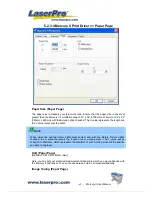
Page 63: ...the Y value represents the width NOTE When using the optional rotary attachment system and with the Rotary Fixture option checked the X value represents the length of your working piece The Y value will be changed to Diameter which represents the diameter of your working piece at the position you wish to engrave Unit Paper Page DEFAULT SETTING Metric mm Here you can set your preferred measurement ...

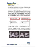
Page 64: ...he image tuning setting In the diagram below the arrows refer to the direction the lens carriage is moving to generate that engraved line If the first and every other line protrude to the left of the square s ideal edge you will want to set the image tuning to a negative value If the first and every other consecutive line protrude to the right of the square s ideal edge you will want to set the im...

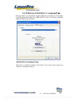
Page 65: ...nguage displayed by the Mercury II Print Driver Current language options allow for English Spanish French and Chinese Simplified Traditional Japanese and German Uninstall Driver Language Page Select this to uninstall the Mercury II print driver You will then need to restart your computer to complete the process ...

Page 66: ...LT SETTING 0 This provides a quick and easy way to immediately adjust the contrast of an engraved image Moving the slider to the Dark setting will increase the contrast levels of the engraved output whereas moving the slider to the Light setting will decrease the contrast levels of the engraved output TIP There are other ways to adjust an engraved image s contrast such as adjust the power speed se...

Page 67: ...ot Bayer Corner 45 Degree DEFAULT SETTING Dot Each pattern type uses a different shape and arrangement of dots to compose the shading effect of a raster image The following diagram is an example of the raster effects when using the different pattern types Dot Bayer Corner o Dithering Matrix Variable depending on the Pattern Type selected DEFAULT SETTING 8x8 This controls the resolution dot size an...

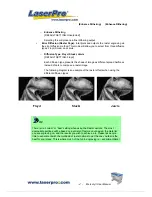
Page 68: ...pe presents the shade of image as different spread halftones instead of dots to compose a raster image The following diagram is an example of the raster effects when using the different diffusion types Floyd Stucki Jarvis TIP There is no correct or best setting when using the Raster options The most appropriate settings will be based on a variety of factors your design the material you are engravi...

Page 69: ...sible when you have selected the Stamp Mode from the Option Page TIP Functions located on the other pages that are useful when making a stamp Set Shoulder Pitch Border Invert and Mirror Pitch Stamp Page Your stamp will be a reversed image composed of engraved depressions and ridges Think of these ridges as the contact sections of the stamp If the ridges of these contact sections are too thin they ...

Page 70: ...Power Level Stamp Page Another important aspect of creating a stamp is setting the slope level of the shoulder The shoulder is the section from the contact section of the stamp to its base This function allows you to adjust the slope for the shoulder sections of your stamp By sliding the sliders or directly input of power levels you will be able to change the slope of the shoulder NOTE The visual ...

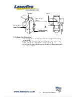
Page 71: ... in the bearing tracks 4 Bearings Hold a dampened cotton swab against the bearing and moving the motion system by hand to clean each bearing 5 Mirrors and Lens The focus lens and the mirror located on the carriage are the two components most likely to require frequent cleaning Caution Don t scratch out the soft coating of the mirror s surface Excessive cleaning the mirrors and lens may cause damag...

Page 72: ...71 Mercury II User Manual INCORRECT Do not use cotton swab to rub clean the mirror CORRECT Lens Tissue Pull the tissue one direction gently after the cleaner has been absorbed evenly Lens Cleaner CORRECT ...

Page 73: ...ly 2 Flood the focus lens with lens cleanser on both sides then using a cotton swab or lens tissue to dry off the remaining solution gently 3 Do not touch the lens surface with your bare hands or press down hard with any cleaning material Remove Front Cover Mirror L Loading hole for manual focal tool Auto focus gauge Focal Sharp Top Screw ...

Page 74: ... 2 Non operational Problems z Laser beam does not generate 1 If the red alignment beam is not revealed the laser beam is misalignment Adjust reflection mirrors for exact focus 2 If the red alignment beam is revealed please check the driver power The laser power may be too low to be detected Please increase the percentage setting of the Laser Power from the software driver or the control panel 3 Pl...

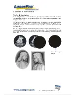
Page 75: ...ready choose 3D Effect as the output mode in the driver Sometimes some material shows better effect if you run the job with 2nd pass with laser out of focus Especially with acrylic the 2nd pass will smooth out the surface For engraving wood as it burns easily and leaves blackened surface after the 1st pass it is necessary to run the 2nd pass to remove the burned surface To do that simply fill the ...

Page 76: ... Lens 2 inch Step Speed Power DPI PPI Focus Remarks 1 25 100 600 auto Auto Focus 3D Mode Engraving 2 25 100 600 auto Lower down table 2 5mm 3D Mode Engraving 3 100 100 600 800 Lower table again 2 mm Black and White Mode Polishing 4 0 2 100 500 auto Move table up 1 3mm Cutting off ...

Page 77: ...Up to 16 color linked power settings per job Z Axis Movement Automatic Resolution DPI Available 200 250 300 500 600 1000 Computer Interface Standard printer port and RS232 to USB Adapter Memory Buffer 16MB standard Upgradeable to 64MB Display Panel 4 line LCD panel showing current file name total working time laser power engraving speed file s loaded into memory buffer setup and diagnostic menus S...

Reviews: