2-1
2
2
:
:
I
I
n
n
s
s
t
t
a
a
l
l
l
l
a
a
t
t
i
i
o
o
n
n
This chapter provides instructions for installing the SCS. It includes the following
topics:
Topic
Page
Physical Installation
2-1
Power 2-2
Connecting a Terminal
2-3
Connecting to a Device Port
2-4
Connecting the Network Port
2-5
Connecting the Modem Port (SCSxx20)
2-5
Power Manager Interface
2-6
Caution:
To avoid physical and electrical hazards, please be sure to
read
Safety Precautions
on page iii before installing the SCS.
Physical Installation
You can install the SCS either in an EIA-standard 19-inch rack (1U tall) or as a
desktop unit. For desktop use, you may remove the rack mount brackets and use
the four rubber feet provided.
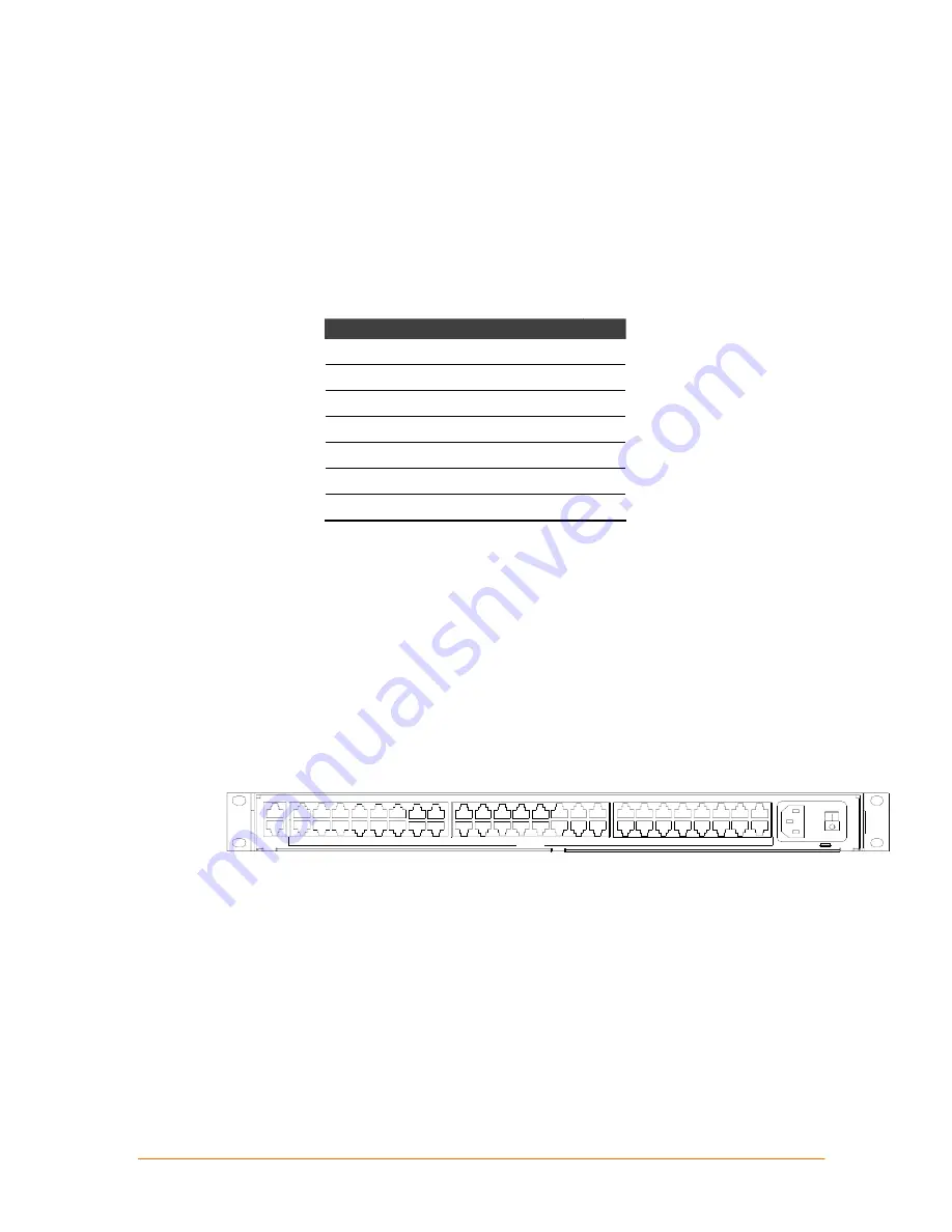
Make all physical connections to the rear of the SCS. You may use the backlit
front-panel LCD display during initial setup and to view current network settings.
Figure 2-1. SCS4805 Rear Panel Connections and Labels (with Rack-Mount Brackets
)
38
14
CON SO LE
3
2
1
8
7
6
5
4
12
13
11
9
10
DE VIC ES
25
N ETW ORK
27
26
30
2 9
28
3 2
31
35
34
3 3
37
36
19
17
18
1 6
15
23
24
21
2 0
22
1 00- 2 40V ~, .5A , 50/ 60 Hz
T 4A, 2 50 VA C
43
4 0
39
42
41
45
4 4
48
46
47
Cau ti on! Rep l ac e with s am e ty pe and r atin g fu s e .
The SCS uses convection cooling to dissipate excess heat.
Note:
Be careful not to block the air vents on the sides of the unit. If you
mount it in an enclosed rack, we recommended that the rack have a
ventilation fan to provide adequate airflow through the unit.
Summary of Contents for SCSxx05
Page 10: ...ix ...
Page 11: ...x ...
Page 12: ...xi ...
Page 13: ...xii ...
Page 14: ...xiii ...
Page 15: ...xiv ...
Page 47: ...SCSxx05 SCSxx20 User Guide 4 Configuration 4 7 ...


