background image

1P480rev0718

07/2018 – Present

LANDOLL COMPANY, LLC

1900 North Street

Marysville, Kansas 66508

(785) 562-5381

800-428-5655 ~ WWW.LANDOLL.COM

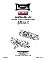
Sure Stand Seeder

Models SSB, SSP and SSBP

 8’, 10’ and 12’

Operators Manual

Summary of Contents for Brillion SSB

Page 1: ...480rev0718 07 2018 Present LANDOLL COMPANY LLC 1900 North Street Marysville Kansas 66508 785 562 5381 800 428 5655 WWW LANDOLL COM Sure Stand Seeder Models SSB SSP and SSBP 8 10 and 12 Operators Manua...

Page 2: ......

Page 3: ...3 Prepare for Emergencies 1 3 Tire Safety 1 3 Safety Chain 1 4 Safety Decals 1 5 2 Assembly 3Pt Seeder Assembly 2 2 Pull Type Seeder Assembly 2 4 Tire and Wheel Installation 2 5 Hydraulics 2 6 Purge...

Page 4: ...ydraulic Lift System 3 7 Transmission Electric Clutch Optional 3 7 Seed Rate Adjustment 3 8 Transmission Drive Bolt 3 12 Calibration for Unlisted Seeds 3 12 Speed Up Kit 3 14 Rear Agitator Seed Box Se...

Page 5: ...iii Agitator Box Slide 4 8 LED Warning Lamps 4 8 Acre Meter Troubleshooting 4 9 Storage 4 9 Service Tip for Brome Box 4 10 5 Reference Tables and Specifications...

Page 6: ......

Page 7: ...ion dealer If items covered in this manual are not understood contact your local Brillion Dealer Warranty Registration Brillion Farm Equipment by Landoll shall have no warranty obligation unless each...

Page 8: ...l laws When transporting the machine on a road or highway use adequate warning symbols reflectors lights and slow moving vehicle sign as required Slow moving tractors and towed machines can create a h...

Page 9: ...or suspected leaks Any fluid injected into the skin must be surgically removed within a few hours or gangrene may result Avoid the hazard by relieving pressure before disconnecting hydraulic lines NOT...

Page 10: ...achine 3 Attach the chain to the Tractor Drawbar Support or specified anchor location Never attach the chain to an intermediate support Allow only enough slack in the chain to permit turning The dista...

Page 11: ...75 725 27 5 6 5 0 7 3 5 6 287 5217 03257 17 6 1 87 62 48 33 25 5 6 6 5 25 1 83 85 72 2 62 0 586 7 7256 3 5 1 3 1 3 3 17 1 5 7 6 25 7 725 5 5 2 1 3281 6 3 5 5 5 7 6 5 25 7227 5 9 5 28 7 6 9 8 6 25 7227...

Page 12: ...1 6 1P480rev0718 INTRODUCTION AND SAFETY INFORMATION Figure 1 4 Safety Decals Locations 3K706 9J302...

Page 13: ...INTRODUCTION AND SAFETY INFORMATION 1P480rev0718 1 7 Figure 1 5 Safety Decals Locations 8 Foot Models 3...

Page 14: ...1 8 1P480rev0718 INTRODUCTION AND SAFETY INFORMATION Figure 1 6 Safety Decals Locations 10 Foot Models 3...

Page 15: ...INTRODUCTION AND SAFETY INFORMATION 1P480rev0718 1 9 Figure 1 7 Safety Decals Locations 12 Foot Models 3...

Page 16: ...1 10 1P480rev0718 INTRODUCTION AND SAFETY INFORMATION Figure 1 8 Safety Decals Locations SD 8 Models 3...

Page 17: ...INTRODUCTION AND SAFETY INFORMATION 1P480rev0718 1 11 Figure 1 9 Safety Decals Locations SDP 8 Models 3...

Page 18: ...1 12 1P480rev0718 INTRODUCTION AND SAFETY INFORMATION Figure 1 10 Safety Decals Locations SD 10 Models 3...

Page 19: ...INTRODUCTION AND SAFETY INFORMATION 1P480rev0718 1 13 Figure 1 11 Safety Decals Locations SDP 10 Models 3...

Page 20: ...1 14 1P480rev0718 INTRODUCTION AND SAFETY INFORMATION Figure 1 12 Safety Decals Locations SD 12 Models 3...

Page 21: ...INTRODUCTION AND SAFETY INFORMATION 1P480rev0718 1 15 Figure 1 13 Safety Decals Locations SDP 12 Models 3...

Page 22: ...1 16 1P480rev0718 INTRODUCTION AND SAFETY INFORMATION Table provided for general use NOTES...

Page 23: ...all working parts move freely bolts are tight and cotter pins spread Refer to the Torque Table for proper torque valves Note the different torque requirements for bolts with lock nuts See Page 4 1 Le...

Page 24: ...tall SMV Mount to Seed Box Center Bracket with 1 2 13 x 1 1 2 Bolts and Locknuts See Figure 2 1 Figure 2 1 SMV Mount CAUTION 5 Be sure Parking Pin is locking Rear Roller down and raise the Seeder See...

Page 25: ...ASSEMBLY 1P480rev0718 2 3 Figure 2 4 Attach 3Pt Hitch RVH ODPS 0DQXDO ROGHU 3W LWFK 1XW RFN DVKHU 8 ROW UDPH 2S 3W LWFK...

Page 26: ...acket Attach Drawbar to Seeder Frame Tube with 5 8 11 U Bolts Lock Washers and Nuts See Figure 2 6 3 Attach the Hose Holder to the Drawbar with 5 8 11 x 1 1 2 Bolt Lock Washer and Nut 4 Install Manual...

Page 27: ...heck the Wheel Bolts for proper torque after this interval and re tighten them The Seeder uses 9 5L x 15 8Ply machine Rib Rating Tires and should be inflated to 44 PSI Install a Tire and Wheel Assembl...

Page 28: ...free to swivel Connect top Hydraulic Hose to the Cylinder Base and bottom Hydraulic Hose to the Cylinder Rod End Position the Hydraulic Hoses so that the Cylinder Base End points downward and the Cyl...

Page 29: ...ASSEMBLY 1P480rev0718 2 7 Figure 2 11 Drawbar Hydraulic Hoses UDZEDU 7RS 3ODWH ROW UDPH RVH ODPS 3DLU RVH VVHPEO...

Page 30: ...Seeder to verify that both Cylinders are working throughout the stroke Fully extend the Lift Cylinders and continue to hold the lever until both Cylinder Rod movement stops Raise Lower Seeder 5 times...

Page 31: ...ASSEMBLY 1P480rev0718 2 9 Table provided for general use NOTES...

Page 32: ...he front right side of the Frame Tube up the outer Light Bracket and plug the 2 prong cord into the Amber Lamp Plug the 3 prong cord into the Red Lamp 10 Repeat for the Left Side Yellow Tape 11 Connec...

Page 33: ...R OHFW UDZEDU LJKW 0RGXOH ROW 7LH UDS DPS DUQHVV RFNQXW RFN DVKHU ROW 5HG DPS PEHU DPS ROW LJKW UDFNHW RFNQXW DPS DUQHVV 609 ROW ODW DVKHU RFNQXW 609 0RXQW RFN DVKHU RFNQXW ROW LJKW UDFNHW RFNQXW PEH...

Page 34: ...ntinue routing the 2 prong cord along the front Frame Tube up the outer Light Bracket and plug into the Amber Lamp 9 Repeat for the Left Side Yellow Tape 10 Connect the 7 Pin Harness into the Light Mo...

Page 35: ...dels PEHU DPS ROW ROW LJKW UDFNHW RFN DVKHU 1XW 7LH UDS 0RGXOH UDFNHW LJKW 0RGXOH ROW 3LQ DUQHVV RQQHFWRU ROGHU ROW ODW DVKHU RFNQXW RFNQXW 0RXQW 7LH UDS ROW RFNQXW RFNQXW LJKW UDFNHW ROW 609 ROW 5HG...

Page 36: ...utch will make a clicking sound Set Seeder on the ground and drive a short distance while turning Toggle Switch to Seed and No Seed The Seed Shaft will stop rotating when Toggle Switch is turned to No...

Page 37: ...ASSEMBLY 1P480rev0718 2 15 Table provided for general use NOTES...

Page 38: ...ach the Pick up Switch Bracket to the front of the Transmission 4 Attach the Pick up Switch to the top of the Pick up Switch Bracket with two 8 32 x 1 1 4 Machine Screws Flat Washers Lock Washers and...

Page 39: ...with the Adhesive Mounting Plates and Tie Wraps to prevent the Cords from becoming entangled or rubbing moving parts 11 Program the Acre Meter See Settings for Loup Acre Meters on page 3 18 Figure 2 2...

Page 40: ...not over tighten 3 Identify the seed cups on either side of the Magnet Wheel Assembly and remove the 1 4 20 hardware 4 Insert Sensor into Shaft Sensor Bracket slot Note 8 and 10 foot seeders use Senso...

Page 41: ...7DSSLQJ LVWLQJ 1XW 6KDIW 6HQVRU UDFNHW 6HHG 6KDIW 6HQVRU LVWLQJ RFN DVKHU 0DFKLQH 6FUHZ 6HQVRU UDFNHW 6SDFLQJ 6FUHZ 6HOI 7DSSLQJ 6HHG 6KDIW 0DJQHW KHHO VVHPEO 6T 6KDIW 0DFKLQH 6FUHZ LVWLQJ RFN DVKHU...

Page 42: ...se 5 Align the Shaft Sensor Bracket with the two Bolts Secure with Flat Washers Lock Washers and Nuts 6 Slide Position Seed Shaft Sensor so it is 1 8 from the magnet See Figure 2 25 7 Tighten both Ret...

Page 43: ...8 x 2 Bolts Secure with Flat Washers and existing Lock Washers and Nuts 11 Insert Sensor into Shaft Sensor Bracket slot 12 Slide Position Seed Shaft Sensor so it is 1 8 from the magnet See Figure 2 27...

Page 44: ...a 2 Pin Shroud and Cavity Plug to protect it from the environment See Figure 2 29 6 Connect plug labeled Left Front Seed Shaft Sensor to the left front Seed Shaft Sensor 7 If you have a double box see...

Page 45: ...ASSEMBLY 1P480rev0718 2 23 Table provided for general use NOTES...

Page 46: ...ee Figure 2 30 2 Install coupling on transmission output shaft and secure with 1 4 x 1 1 2 Roll Pin See Figure 2 31 3 Loosen U Bolts which fasten front seed box to frame at center and right end Replac...

Page 47: ...ar of boxes so the pin in the bottom of each handle engages the slotted hole in the slide Attach handles to shift plates using 1 2 x 1 Pivot Bolt and Flat Washer Tighten Bolt just so the handle can mo...

Page 48: ...hes See Figure 2 36 NOTE The standard Agitator Box Kit comes with blade agitators Optional brush or cage agitators are also available See Page 2 27 for information on these options Figure 2 36 Shaft R...

Page 49: ...fts End Washers and Retainer Plate See Figure 2 38 5 Apply Important Decal 5D505 to the Front Seed Box visible by the Tractor Driver See Figure 2 37 Figure 2 37 Decal 5D505 Figure 2 38 Agitator The br...

Page 50: ...ssion differences See Figure 2 39 NOTE For installation of the Blade Cage Agitator See Brush Agitator Installation Optional on page 2 26 Figure 2 39 Shaft Rotation Seed Box Dividers 1 Use upper and lo...

Page 51: ...arning Lamp Installation Dimensions PEHU DPS 5HG DPS 5HG DPS PEHU DPS 3W 0DFKLQHV LJKW UDFNHW LJKW UDFNHW 609 609 0RXQW W 2QO W 2QO OO 3W 0RGHOV OO 3W 0RGHOV PEHU DPS 5HG DPS 5HG DPS PEHU DPS UDZEDU 0...

Page 52: ...amp Continue routing the 2 prong cord along the front of Frame Tube up the outer Light Bracket and plug it into the Amber Lamp 8 Repeat for the Left Side Yellow Tape 9 8 Ft and 10 Ft Models Connect th...

Page 53: ...on Drawbar Model RFNQXW RFNQXW 6 2S3XOY OHFW UDZEDU RQQHFWRU ROGHU 609 7LH UDS 0RXQW ROW ODW DVKHU 609 0RXQW ROW ODW DVKHU 3LQ DUQHVV 0RGXOH UDFNHW LJKW 0RGXOH DPS DUQHVV 7LH UDS ROW ROW RFNQXW LJKW U...

Page 54: ...e routing the 2 prong cord along the front of Frame Tube up the outer Light Bracket and plug it into the Amber Lamp 8 Repeat for the Left Side Yellow Tape 9 8 Ft and 10 Ft Models Connect the Lamp Harn...

Page 55: ...Light Installation RQQHFWRU 6 2S3XOY OHFW 3W ROW 7LH UDS DPS DUQHVV 0RGXOH UDFNHW LJKW 0RGXOH RFNQXW 5HG DPS PEHU DPS 609 LJKW UDFNHW RFNQXW PEHU DPS ROW 5HG DPS PEHU DPS 7LH UDS 0RXQW ROW ODW DVKHU...

Page 56: ...s to the Brackets with 1 2 13 x 3 1 4 x 4 9 16 U Bolts Lock Washers and Nuts Do Not tighten at this time 3 Attach the Scraper Angle to the LH and RH Angle Brackets with 1 2 13 x 1 1 4 Bolts Flat Washe...

Page 57: ...er Kit QJOH UDFNHW 6HHGHU UDPH 7XEH HQWHU 6FUDSHU 6FUDSHU ODW DVKHU RFN DVKHU 1XW DUULDJH ROW 6FUDSHU QJOH QJOH UDFNHW 8 ROW UDFNHW 8 ROW RFN DVKHU 1XW ODW DVKHU RFN DVKHU 1XW ROW 5 QJOH UDFNHW 6FUDSH...

Page 58: ...raps 1 2 13 x 6 Bolts Lock Washers and Nuts See Figure 2 47 3 Center Tooth Tube in relationship with the Drawbar or 3Pt Hitch and Tighten U Bolts 4 Attach the S Tines onto the Tooth Tube in the desire...

Page 59: ...48 S Tine Track Remover Kit Optional 6HHGHU UDPH 7XEH 8 ROW RFN DVKHU 1XW 6 7LQH UDFNHW DUULDJH ROW 7RRWK 7XEH ODQJH RFNQXW XFN RRW 3RLQW 5HYHUVLEOH 3RLQW 3ORZ ROW 1XW RFN DVKHU 6 7LQH RFNQXW 6WUDS R...

Page 60: ...eldment to the Adjusting Angles with 1 2 13 x 1 3 4 Bolts and Locknuts Tighten the Locknuts to allow free side to side swinging 7 Center each Coil Tine Track Remover Assemble behind the Tractor Tires...

Page 61: ...al 8 ROW 1XW RFN DVKHU UDFNHW ROW ROW RFNQXW UP HOGPHQW ODW DVKHU RFN DVKHU 1XW RLO 7LQH 5RXQG DU ROW RFN 6FUHZ GMXVWLQJ QJOH 6HHGHU UDPH 7XEH ODW DVKHU RFN DVKHU 1XW ROW GMXVWLQJ QJOH KDLQ DLU 3LQ RW...

Page 62: ...2 40 1P480rev0718 ASSEMBLY Table provided for general use NOTES...

Page 63: ...ilure to do so can result in serious injury or death and cause damage to the equipment When transporting the unit place cylinder lockouts in the transport lock position after fully extending the cylin...

Page 64: ...sulting in a poor germination 5 Set Lift Rod length long enough to ensure Seeder can float downward in the case of a furrow or waterway Lower Links should be the same height leveling your Brillion See...

Page 65: ...OPERATION 1P480rev0718 3 3 Figure 3 1 3 Point Hitch DWHJRU UHH LQN 3LQ 3LQ DWHJRU 1DUURZ 4XLFN RXSOHU 3LQ 3LQ XVKLQJ XVKLQJ DWHJRU 4XLFN RXSOHU 3LQ 3LQ XVKLQJ XVKLQJ 2S DUJH6HHGHU 3W LWFK...

Page 66: ...Seeder 1 With Seeder raised remove the Klik Pin push in the Parking Pin replace the KIik Pin See Figures 3 2 and 3 4 2 Disconnect the Tractor from Seeder lower Seeder Figure 3 3 Parking Pin Disengaged...

Page 67: ...he safety chain should latch securely to prevent it from coming loose See Figure 3 6 Figure 3 6 Safety Chain 6 Connect the 7 Pin Connector to Tractor Outlet routing cable by avoiding pinch points Make...

Page 68: ...ansport Locks in the engaged position over the Cylinder Rod Secure with the Clevis Pins and Hairpin Cotters See Figure 3 5 4 Transport the Seeder to the area to be seeded 5 Disengage each Transport Lo...

Page 69: ...re water or air to clean the Electric Clutch as damage could occur The Electric Clutch is controlled by a Toggle Switch on the Clutch Switch Box that is mounted to the Tractor The Electric Clutch is d...

Page 70: ...g Screw See Figure 3 10 IMPORTANT Do Not Loosen or Adjust the 1 2 13 Locknut See Figure 3 10 Figure 3 10 Seed Box Seed Rate Adjustment 1 To increase the rate of seeding loosen the 1 8 Nut on inside of...

Page 71: ...6 9 13 17 21 24 28 CLOVER ALYCE CALIFORINA BUR CRIMSON HUMBAM 2 5 8 12 17 20 24 30 CRESTED WHEAT 1 2 3 4 5 6 7 CROWN VETCH 2 7 11 15 20 24 29 34 FLAX 2 5 8 10 13 16 19 21 HARDING GRASS 1 4 6 9 11 14 1...

Page 72: ...6 9 13 17 21 24 28 CLOVER ALYCE CALIFORNIA BUR CRIMSON HUMBAM 2 5 8 12 17 20 24 30 CRESTED WHEAT 1 2 3 4 5 6 7 CROWN VETCH 2 7 11 15 20 24 29 34 FLAX 2 5 8 10 13 16 19 21 HARDING GRASS 1 4 6 9 11 14 1...

Page 73: ...3 19 24 30 34 40 CLOVER ALYCE CALIFORNIA BUR CRIMSON HUMBAM 3 7 11 17 24 28 34 43 CRESTED WHEAT 1 3 4 6 7 9 10 CROWN VETCH 3 10 16 21 29 34 41 49 FLAX 3 7 11 14 19 23 27 30 HARDING GRASS 1 6 9 13 16 2...

Page 74: ...x Cover NOTE The information listed in the Seed Charts is subject to change without notice IMPORTANT Rates are for the 13 Tooth Driver Double these values for the 26 Tooth Driver See Figure 3 13 Front...

Page 75: ...OPERATION 1P480rev0718 3 13 Figure 3 12 Transmission Drive 7RRWK ULYHQ 7RRWK ULYHQ 7RRWK ULYHU 7RRWK 2SWLRQDO H 7LJKWHQHU...

Page 76: ...Shaft 3 Remove the 1 4 x 1 1 2 Roll Pin from 13 Tooth Sprocket Hub on the Front Transmission Shaft 4 Remove the Locking Collar from the left side of the Front Transmission Shaft 5 Move the shaft far e...

Page 77: ...e Cage agitators are provided with you seeder for versatility Brush agitators are also available to order for specific varieties Cage Agitators can be used to plant cereal grains such as wheat oats ry...

Page 78: ...river double these values for 26 tooth driver 1 Rates are intended as a guide only variations in seed size and cleanliness will affect rates check acreage and pounds of seed used for best results 2 Ca...

Page 79: ...OPERATION 1P480rev0718 3 17 Figure 3 15 Rear Agitator Seed Chart...

Page 80: ...OTAL LEDs are lit The digits indicate the acres covered since the total acre counter was cleared To clear the total acre count press and hold the UP and DOWN buttons for two seconds If a password has...

Page 81: ...ero 0000 to scroll to other modes or screens To reset the FIELD ACRES screen to zero 0000 press the up and down buttons simultaneously To Program Meter 1 Press the function button to scroll to pulses...

Page 82: ...0 314 10 0 SLP12 SL12 314 12 0 SLP204 2041 SLPB204 2041 128 4 0 SLP206 2061 SLPB206 2061 128 6 0 SLP304 3041 SLPB304 3041 64 4 0 SLP306 3061 SLPB306 3061 64 6 0 LSP5 128 5 0 LSP6 128 6 0 LSS6 128 6 0...

Page 83: ...64 12 SSP308 SS308 382 8 SSP310 SS310 382 10 SSP312 SS312 382 12 SLP8 SL8 4147 8 SLP10 SL10 4147 10 SLP12 SL12 4147 12 SLP204 SLP2041 1690 4 SLP206 SLP2061 1690 6 SLP304 SLP3041 845 4 SLP306 SLP3061 8...

Page 84: ...eight should not exceed more than 1 5 times the tractor weight Maximum transport speed for the Seeder is 20 mph for the machine CAUTION 3 When towing equipment in combination the maximum equipment gro...

Page 85: ...port during daylight hours whenever possible Always use flashing warning lights except where such use is prohibited by law Make sure lights reflectors and SMV emblem are clearly visible and operating...

Page 86: ...3 24 1P480rev0718 OPERATION Table provided for general use NOTES...

Page 87: ...50 65 81 90 112 9 16 12 55 62 80 100 110 137 9 16 18 60 75 90 112 130 162 5 8 11 75 94 110 137 170 212 5 8 18 85 106 130 162 180 225 3 4 10 130 162 200 250 280 350 3 4 16 150 188 220 275 320 400 7 8 9...

Page 88: ...sure lubricants are used When fasteners are dry solvent cleaned add 33 to as received condition torque Bolt head identification marks indicate grade and may vary from manufacturer to manufacturer Thic...

Page 89: ...not install the Seal into the Hub NOTE The Single Lip Seals should point away from the Hub to keep contaminants out and allow grease to pass 7 Slide the Inner Bearing Cone and Hub onto the Spindle 8...

Page 90: ...Lubrication Intervals UV UV URQW 5ROOHU HDULQJ 5HDU 5ROOHU HDULQJ 3W 6HHGHU UDPH KHHO UP KHHO XE 5HSDFN QQXDOO UV UV 7XUH DQG KHHO VVHPEO 3XOO 7 SH UDPH URQW 5ROOHU HDULQJ UV 3XOO 7 SH 6HHGHU UDPH 5H...

Page 91: ...Clamp Bands Tighten the Clamp Band Socket Head Bolt Clamp Band open section over Roller Drum weld seam to 75ft lbs Thereafter check Front and Rear Roller Assemblies every 50 100 hours IMPORTANT To max...

Page 92: ...deflection See Figures 4 4 and 4 5 NOTE The Vertical chain drive for the optional Seed Box Agitator should be adjusted so both spans of chain are almost taut Move the Chain Tension Bar on the inside...

Page 93: ...eed Shaft to close all Seed Meters Tighten 1 2 13 Locknuts against Adjusting Screw 2 Seed Box Feed Roll Coupling which joins the left and right Seed Shafts changes Seed Meters on the left Seed Box in...

Page 94: ...vered at the 0 position Figure 4 9 Control handle at 6 LED Warning Lamps When plugging in the Lamp 7 Pin Warning Lamp Connector 1 Make sure the Tractor has a good clean Receptacle free of dirt and cor...

Page 95: ...nected to the display and see if the display increments up If not put an ohm meter or continuity tester on the contacts of the Pick up Switch harness and place a magnet in front of the Pick up Switch...

Page 96: ...y See Figure 4 12 Check that Seed Boxes are level and straight from end to end Loosen and adjust Seed Boxes from the center and right hand end brackets if necessary It may also be necessary to make an...

Page 97: ...Tables and Specifications Table 5 1 8 Foot Models W W t t t d t d d Z d K K D Z D D D D K t d t d W Z W Z Z W W W Z W d d d W E Y W E d W Z E K K d t d Z K K Z K K D K K h K K K K K D K K t Ds E W W Z...

Page 98: ...ABLES AND SPECIFICATIONS Table 5 2 10 Foot Models W W t t t d t d d Z d K K D Z D D D D K t d t d W Z W Z Z W W W Z W d d d W E Y W E d W Z E K K d t d Z K K Z K K D K K h K K K K K D K K t Ds E W W Z...

Page 99: ...FICATIONS 1P480rev0718 5 3 Table 5 3 12 Foot Models W W t t t d t d d Z d K K D Z D D D D D D K t d t d W Z W Z Z W W W Z W d d d W E Y W E d W Z E K K d t d Z K K Z K K D K K h K K K K K D K K t Ds E...

Page 100: ...5 4 1P480rev0718 REFERENCE TABLES AND SPECIFICATIONS Table provided for general use NOTES...

Page 101: ...ement s Description and Comments 07 2008 205rev0708 Initial Release 07 2011 205rev0711 Updated Pictures and Drawings Incorporated ECN 35017 09 2013 205rev0913 Added LED Warning Lights 07 2018 0718 Upd...

Page 102: ...Seeder Models SS SSB SSP and SSBP 8 10 and 12 Operator s Manual Re Order Part Number 1P480rev0718 LANDOLL COMPANY LLC 1900 North Street Marysville Kansas 66508 785 562 5381 800 428 5655 WWW LANDOLL C...

Reviews: