OPERATING INSTRUCTIONS
3-23
4.
To operate the remote:
a.
Press and hold the POWER button for at least 2
seconds and release.
b.
The transmitter is designed with a power saving
feature which turns the transmitter off after 15
minutes if no buttons are pressed.
c.
There are red and green LED’s both on the
keypad of the transmitter and inside the receiver
case. The green LED will blink 2 times per
second when the transmitter and receiver are
communicating. It will blink 1 time per second if
there is no communication (i.e. - no power to the
receiver).
d.
The red LED on the transmitter and in the
receiver will blink if there is a shorted or open
output. Refer to
and
count the number of blinks to determine the
output with the fault.
e.
The transmitter’s red LED blinks 1 time per
second if the batteries are low and need to be
replaced. To confirm a low battery condition, turn
the receiver off and leave the transmitter on. If
the transmitter red LED continues to blink, the
battery is low and requires replacement. If the
red LED blinks only when the receiver is on,
there is a fault with one or more outputs, as
stated above.
f.
The red LED will stay on while charging and
when the charge is completed the green LED will
stay on.
g.
It will take longer to charge if the transmitter is on
during charging.
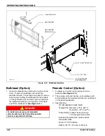
Figure 3-15: Remote Control Transmitter
Table 3-1: Transmitter Error Code Chart
Table 3-2: Receiver Error Code Chart
5.
Synchronizing transmitter and receiver:
There are over 64,000 different addresses (id codes)
available for each transmitter and receiver pair. Each
transmitter and receiver pair is synchronized together at
the factory. If a new transmitter is needed, synchronizing
is required. Use the following procedure:
a.
With power applied, press the red button on the
receiver for >5 seconds until LED’s toggle.
b.
With the transmitter off, press and hold the
POWER button for >10 seconds until LED’s blink,
then release.
c.
Wait for a few seconds until the green LED’s
begin to blink.
d.
Teach complete.
IMPORTANT
On winches with the air tension option, the winch
tension is engaged automatically when the switch is
turned to winch in/out. The winch tension switch on
either the remote or the control panel must be used
to disengage the winch.
TRANSMITTER
6 FUNCTION
DECAL
RED ERROR
CODE LIGHT
GREEN SIGNAL
LIGHT
400b remote control op
Transmitter Error Code Chart
Error Code
Probable Cause
1
Low Battery
2
Tilt Down Fault
3
Tilt Up Fault
4
Winch Out Fault
5
Winch In Fault
6
Axle Back Fault
7
Axle Ahead Fault
Receiver Error Code Chart
Error Code
Probable Cause
1
RF Communication Problem
2
Tilt Down Fault
3
Tilt Up Fault
4
Winch Out Fault
5
Winch In Fault
6
Axle Back Fault
7
Axle Ahead Fault
Summary of Contents for 425B Series
Page 2: ......
Page 6: ...iv F 543 1011 Edition...
Page 14: ...2 6 F 543 1011 Edition STANDARD SPECIFICATIONS...
Page 26: ...3 12 F 543 1011 Edition OPERATING INSTRUCTIONS Figure 3 7 Steps for Loading and Unloading...
Page 32: ...3 18 F 543 1011 Edition OPERATING INSTRUCTIONS Figure 3 12 Dock Leveler Operation...
Page 61: ...MAINTENANCE AND LUBRICATION 4 21 Figure 4 13 Axle and Brake Assembly...
Page 76: ...4 36 F 543 1011 Edition MAINTENANCE AND LUBRICATION Page Intentionally Blank...
Page 86: ...5 10 F 543 1011 Edition TROUBLESHOOTING GUIDE...
Page 87: ......


