PAGE
Pellet Grill
26
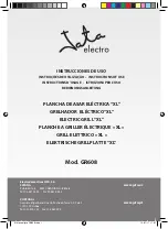
470430 WIRING DIAGRAM
Smoke
225
250
275
300
325
350
400
450
℉
110mm
90mm
Troubleshooting
Control Board Back View
Board Wire Harness
Connection
Digital Control Wiring Diagram
POWER CORD
BLACK
ORANGE
PURPLE
WHITE
WHITE
WHITE
AUGER MOTOR
FIRE POT
BLOWER FAN
PROBE
Off
High
Meat/P
IGNITER
WHITE
WHITE
GRILL PROBE
RED
WHITE
Blower Fan
Igniter
Auger Motor
Power Cord / AC Input
5 amp 120 Volt Fuse w/ Housing
Cartridge Fuse
The circuit board is equipped with a 5 amp, 120 volt fuse to help protect against power
surges and electrical shorts. When not in use, always unplug and store your grill. This will
help prevent electrical damage from power surges or storms.
Grill Probe
connections
Summary of Contents for 470430
Page 6: ...PAGE Pellet Grill 6 1 2 14 15 AA AA CC 1 2 8x 8x Assembly Instructions ...
Page 7: ...PAGE Pellet Grill 7 AA CC AA CC AA CC 25 26 10 10 AA 14 10 10 15 7 11 11 8x 3x 8x 2x 3 4 ...
Page 8: ...PAGE Pellet Grill 8 13 AA AA CC BB DD EE BB 29 29 29 19 DD DD EE 5 6 4x 1x 3x 4x 1x ...
Page 9: ...PAGE Pellet Grill 9 5 AA AA AA AA CC FF FF 23 24 4x 4x 4x 7 8 ...
Page 10: ...PAGE Pellet Grill 10 6 6 8 8 20 20 9 9 27 27 21 21 22 22 9 10 ...
Page 11: ...PAGE Pellet Grill 11 3 2 2 AA AA 4 11 12 2x ...
Page 12: ...PAGE Pellet Grill 12 28 17 GG 16 12 18 HH GG HH 13 14 4x 1x ...
Page 13: ...PAGE Pellet Grill 13 ...