lancer CENTURIONII 85-0055 Installation And Service Manual Download Page 20

(7.3 continued)

B. Check valve not properly

B. Push check valve all the way into

installed in concentrate

concentrate tank.

container.

C. Concentrate pump not

C. Properly install (push in)

properly installed in pump

concentrate pump in pump support.

support.

D. Concentrate pump defective.

D. Repair or replace concentrate

pump.

E. Check valve clogged.

E. Remove and clean check valve.

F. Large lumps in concentrate.

F. Defrost concentrate.

G. Air leak in concentrate inlet

G. 1. Replace both o-rings on check

tube.

valve.

2. Replace concentrate tube.

H. Control PCB defective.

H. Replace control PCB.

I.

Concentrate tube kinked.

I.

Remove kink in tube.

7.4

Concentrate only -

A. Inlet water shut off valve

A. Turn inlet water shut off valve ON.

no water either side.

turned OFF.

B. Inlet water strainer dirty/

B. Remove strainer and clean.

clogged.

C. Water coils frozen.

C. Replace ice bank control.  Check

umbrella check valve in vacuum

breaker and replace if necessary.

D. Water regulator not properly

D. Connect test gauge to each water

set and not passing water.

regulator and reset to proper

pressure.

E. Water solenoid valve not

E. Connect wiring harness to water

connected to wiring.

solenoid valves.

F. Control PCB defective.

F. Replace control PCB.

7.5

Concentrate only -

A. Defective control PCB.

A. Replace control PCB.

no water on one side

B. Water solenoid valve not

B. Connect wiring harness to water

only.

connected to wiring harness.

solenoid valve.

C. Defective coil on water

C. Replace coil.

solenoid.

D. Defective water solenoid

D. Repair or replace water solenoid

valve.

valve.

7.6

No flush water either

A. Flush solenoid valve not

A. Connect wiring harness to water

side, system dispenses.

connected to wiring harness.

flush solenoid valve.

normally.

B. Control PCB defective.

B. Replace PCB.

C. Flush water line from water

C. Unpinch.

regulator pinched.

7.7

No flush water - one

A. Pinched flush water tube of

A. Replace flush water tube.

side only, normal

effected side.

dispense both sides.

B. Defective flush solenoid.

B. Replace flush solenoid.

C. Control PCB defective.

C. Replace control PCB.

7.8

Water drips from spout

A. Defective water solenoid

A. Repair or replace water solenoid

when drink is NOT

valve.

valve.

being dispensed.

7.9

Water leaking into

A. Flush solenoid valve leaking.

A. Repair or replace flush solenoid

concentrate container

valve.

and/or concentrate tube. B. Check valve defective.

B. Repair or replace check valve.

7.10 Water leaking into

A. Check valve leaking.

A. Repair or replace check valve.

concentrate container

during flush cycle.

7.11 Air leaking into

A. Air leaking into check valve

A. Push tube onto check valve.

concentrate tube and/or

from flush and/or concentrate

Replace tube if necessary.

concentrate pump.

tube.

(7.11 continued next page)

TROUBLE

CAUSE

REMEDY

16

Summary of Contents for CENTURIONII 85-0055

Page 1: ...cer Copyright 1992 by Lancer all rights reserved FAX ENGINEERING 210 310 7096 DATE 07 31 92 P N 28 0019 Please refer to the Lancer web site www lancercorp com for information relating to Lancer Instal...

Page 2: ...EM 6 3 7 REFRIGERATION SYSTEM 6 4 RELOCATING OR SHIPPING UNIT 6 4 1 REMOVING AN OPERATING UNIT 6 4 2 TRANSPORTING UNIT 7 4 3 SHIPPING UNIT 7 5 PERIODIC MAINTENANCE 7 5 1 LUBRICATION 7 5 2 CLEANING WAT...

Page 3: ...RTMENT AND INTO DRIP TRAY 17 7 17 COMPRESSOR STARTS AND CONTINUES TO RUN UNTIL FREEZE UP AND WILL NOT CUT OFF 18 7 18 WARM DRINKS 18 7 19 COMPRESSOR DOES NOT START NO HUM CONDENSER FAN MOTOR DOES NOT...

Page 4: ...QUIREMENTS Minimum flowing pressure of 28 PSI 1 76 kg cm2 at a flow rate of three 3 ounces 88 7 ml per second Connection 5 8 inch 18 male flare 3 8 inch flare COMPRESSOR 1 4 HP CONCENTRATE CONTAINER C...

Page 5: ...roduct Plate Limeade 05 0196 1 Product Plate Pineapple 05 0197 1 Product Plate Five Alive 05 0384 1 Product Plate Fruit Punch 05 0385 2 Product Plate Grape 05 0191 2 Product Plate Cranberry 05 0195 2...

Page 6: ...ontainer compartment The overflow water will drain into the drip tray E Replace yellow plug 1 6 CONNECTING TO ELECTRICAL POWER WARNING THIS UNIT MUST BE PROPERLY ELECTRICALLY GROUNDED TO AVOID POSSIBL...

Page 7: ...ay require a slight adjustment at the time of installation This can be accomplished by using a refractometer as follows 1 Dispense a 5 or 6 ounce 147 9 or 177 4 ml cup of product and discard 2 Dispens...

Page 8: ...emove top cover B Place opened can of COMPLETELY THAWED concentrate into concentrate container C When the concentrate low level indicator is sounding the concentrate container can be refilled with the...

Page 9: ...ation Taste dispensed product to ensure there is no off taste If off taste is found additional flushing of dispensing system may be required 3 PRINCIPLES OF OPERATION 3 1 WATER SYSTEM Inlet water is d...

Page 10: ...ld in FLUSH position and a paddle is depressed the electronic system opens the flush solenoid and allows water to flow to the check valve on the concentrate container and simultaneously to operate the...

Page 11: ...a common carrier it must be secured to the plywood shipping base and repacked in the original carton with the inner packaging material For this reason it is wise to retain the original packing materi...

Page 12: ...offs with the alarm positioned between the mode switch and circuit breaker F Turn the plastic latches 1 4 turn clockwise to secure the control board to the control panel G Connect the transformer and...

Page 13: ...emove splash plate D Unplug sensor from harness E Loosen nut on back of sensor F Remove sensor from bracket G Replace with new sensor and adjust so that sensor face is about 1 8 inch about 3 175 mm fr...

Page 14: ...ng motion so as not to damage shaft seal There is only one 1 four hole motor pump body combination There is a small nipple on the pump body that corresponds with a small dimple in the motor casing the...

Page 15: ...POWER CORD FROM THE ELECTRICAL OUTLET A Turn key switch OFF B Close inlet water shut off valve C Remove pump support refer to Section 6 9 D If solenoid is leaking remove nut on end of coil and remove...

Page 16: ...ve B Remove lid over agitator deck C Remove vacuum breaker by loosening adaptor nut on top side of tank assembly D Remove cap from end of vacuum breaker CAUTION USE ONLY LANCER LUBE USE OF OTHER GREAS...

Page 17: ...e procedure 6 17 AGITATOR DECK WARNING DISCONNECT THE POWER CORD FROM THE ELECTRICAL OUTLET A Remove lid over agitator deck B Unplug wiring harness from agitator deck C Remove two 2 nuts holding agita...

Page 18: ...o Section 6 20 B Remove drip tray dispensing paddles and splash plate C Remove eight 8 screws on front of unit four 4 on each side Locations are as follows 1 Top and bottom in flange of control housin...

Page 19: ...properly calibrated charging cylinder Care must be taken to ensure a charge with 1 8 ounce 3 5 g 16 Carefully leak check all solder joints 17 To reassemble reverse above procedure 7 TROUBLESHOOTING C...

Page 20: ...ce control PCB no water on one side B Water solenoid valve not B Connect wiring harness to water only connected to wiring harness solenoid valve C Defective coil on water C Replace coil solenoid D Def...

Page 21: ...noid valve valve 7 14 oBrix varies from drink A Inlet water supply pressure A Correct water supply must be to drink and or flow too low made available B Use of other equipment on B Remove other equipm...

Page 22: ...Replace compressor relay or start no hum no Ice or overload overload bank but condenser fan B Defective compressor B Replace compressor motor runs C Improper or loose wiring C Correct wiring Refer to...

Page 23: ...rt time but diagram shuts off on overload B Low voltage B Measure voltage across common and run terminal on compressor Voltage must not drop below 90 of rated voltage C Excessively high refrigerant C...

Page 24: ...then go OUT immediately This is caused by a high in rush current to get the motor initially started The following are some typical diagnostic light conditions and the possible problems associated with...

Page 25: ...To assure proper installation in converting a Centurion II from paddle dispense to pushbutton dispense complete the following instructions carefully A Centurion unit has a Serve Flush switch so note a...

Page 26: ...ulling on the wires E Remove control panel from control housing F Disconnect the 4 pin mode switch connector and 2 pin transformer connector by grasping the housing Do NOT try to remove by pulling the...

Page 27: ...Lift front cover and push switch to FLUSH position B Close front cover and press DISPENSE pushbutton for desired station to be flushed C After completing flush lift front cover and return switch to SE...

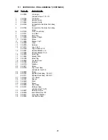
Page 28: ...11 ILLUSTRATIONS PARTS LISTINGS AND WIRING DIAGRAMS 11 1 CENTURION II FINAL ASSEMBLY 24...

Page 29: ...Kit 15 07 0287 Handle Bracket L H 07 0286 Handle Bracket R H 16 05 0209 Hole Plug 17 51 0293 Splash Plate 18 05 0188 Hole Plug 19 04 0240 Thumb Screw 20 05 0186 Retainer 21 04 0179 Washer 22 04 0477 S...

Page 30: ...26 11 2 CENTURION II PUMP REGULATOR ASSEMBLY...

Page 31: ...Pump Assy includes Items 22 29 82 0139 Pump Body Assy includes Items 22 28 22 82 0179 Pump Body Sub Assy 23 04 0169 Screw 24 05 0132 Impeller 25 02 0090 O Ring 26 05 0134 End Cap 27 04 0207 Thumb Scre...

Page 32: ...11 3 CENTURION II WATER CONCENTRATE COMPONENT ASSEMBLY 28...

Page 33: ...Sensor Sub Assy 27 07 0212 Bracket 28 17 0076 Solenoid Assy Dispense 29 47 0279 Tube 30 01 0797 Nut 31 08 0047 Tube Flush Left 32 04 0220 Nut 33 82 0326 Tank Assy 34 50 0086 Insulation Left 35 50 0084...

Page 34: ...30 11 4 CENTURION II REFRIGERATION ASSEMBLY...

Page 35: ...AC 12 0059 Overload 220 VAC 16 12 0026 Relay 120 VAC 12 0060 Relay 220 VAC 17 13 0006 Terminal Cover 18 03 0040 Bale Strap 19 04 0537 Washer 20 03 0150 Clip 21 04 0231 Nut 22 04 0059 Screw 23 51 0161...

Page 36: ...0059 Screw 5 07 0098 Bracket 6 02 0041 Seal 7 05 0142 Sleeve 8 07 0111 Bracket 9 04 0066 Screw 10 52 0155 Harness Assy 11 11 0051 Nut Wire 12 02 0032 Washer 13 05 0031 Propeller 14 04 0062 Protector...

Page 37: ...04 0070 Screw 4 52 0486 Harness Assy 5 88 0025 Sleeve 6 52 0152 Harness Assy 7 13 0025 Strain Relief 8 52 0005 Power Cord Assy 9 52 0149 Lead Assy 10 12 0097 Key Switch 11 52 0565 Key Switch Harness 1...

Page 38: ...11 7 CENTURION II WIRING DIAGRAM 34...

Page 39: ...nd Sub Continent B 7 Pannalal Silk Mill Compounds 78 LBS Marg Bhandup W Mumbai 400 078 India Phone 91 22 2561 6665 Cel No 91 98 2029 5252 FAX 91 22 5637 4018 e mail shafiquis vsnl com Lancer Authorize...

Page 40: ...Las Villas San Nicolas De Los Garza N L Monterrey N L M xico C P 66422 Phone 52 81 83 52 85 32 Phone 52 81 83 52 85 34 Phone 52 81 83 52 53 60 FAX 52 81 83 32 54 10 e mail direccion lancer com mx Lan...

Reviews: